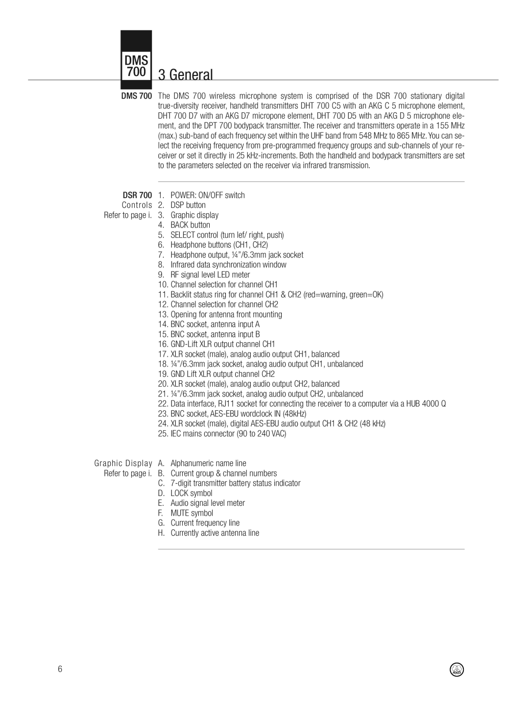
DMS700 specifications
The AKG Acoustics DMS700 is a state-of-the-art digital wireless microphone system that has gained considerable acclaim in the realms of live performance, broadcasting, and professional sound production. Designed to meet the needs of demanding environments, the DMS700 showcases a plethora of features and technologies that enhance its reputation as a leading choice for audio professionals.One of the standout features of the DMS700 is its advanced digital transmission technology. Utilizing the UHF frequency band, this system provides a robust and reliable audio signal, free from the interference that often plagues analog systems. This is complemented by its wide dynamic range, ensuring that audio clarity is maintained across various sound levels, making it ideal for both spoken word and musical performances.
The DMS700 system supports multiple channels, allowing users to operate several microphones simultaneously without fearing frequency collisions. With its intuitive frequency management, the system facilitates quick setup and ensures that all channels can function harmoniously. This is particularly beneficial in environments where multiple performers are using wireless microphones, as it allows for seamless transitions and interference-free operation.
In terms of design, the DMS700 boasts a sleek yet sturdy build tailored for professional use. The receivers feature an easy-to-read LCD display, providing real-time feedback on battery status, signal strength, and frequency information. Additionally, the handheld transmitters are ergonomically designed, allowing for comfortable use over extended periods, which is crucial in live performance scenarios.
Another key characteristic of the DMS700 is its versatility. The system is compatible with a range of AKG microphone capsules, enabling users to customize their setup according to specific performance needs. Whether it's for vocals or instruments, the ability to switch capsules enhances the overall adaptability of the system.
Moreover, the DMS700 incorporates sophisticated encryption technology, ensuring secure transmission of audio signals by protecting against unauthorized access. This feature is especially important for events where confidentiality is essential, further demonstrating AKG's commitment to quality and security in professional audio.
In conclusion, the AKG Acoustics DMS700 digital wireless microphone system is a comprehensive solution designed to meet the evolving demands of audio professionals. With its superior transmission technology, flexible channel management, ergonomic design, and enhanced security features, the DMS700 stands out as a reliable choice for anyone seeking exceptional audio performance in a wireless format. Whether in live settings, studios, or broadcasting, this system is engineered to deliver outstanding sound quality, making it an invaluable tool for sound engineers and performers alike.