Manuals
/
Alamo
/
Lawn and Garden
/
Lawn Mower
Alamo
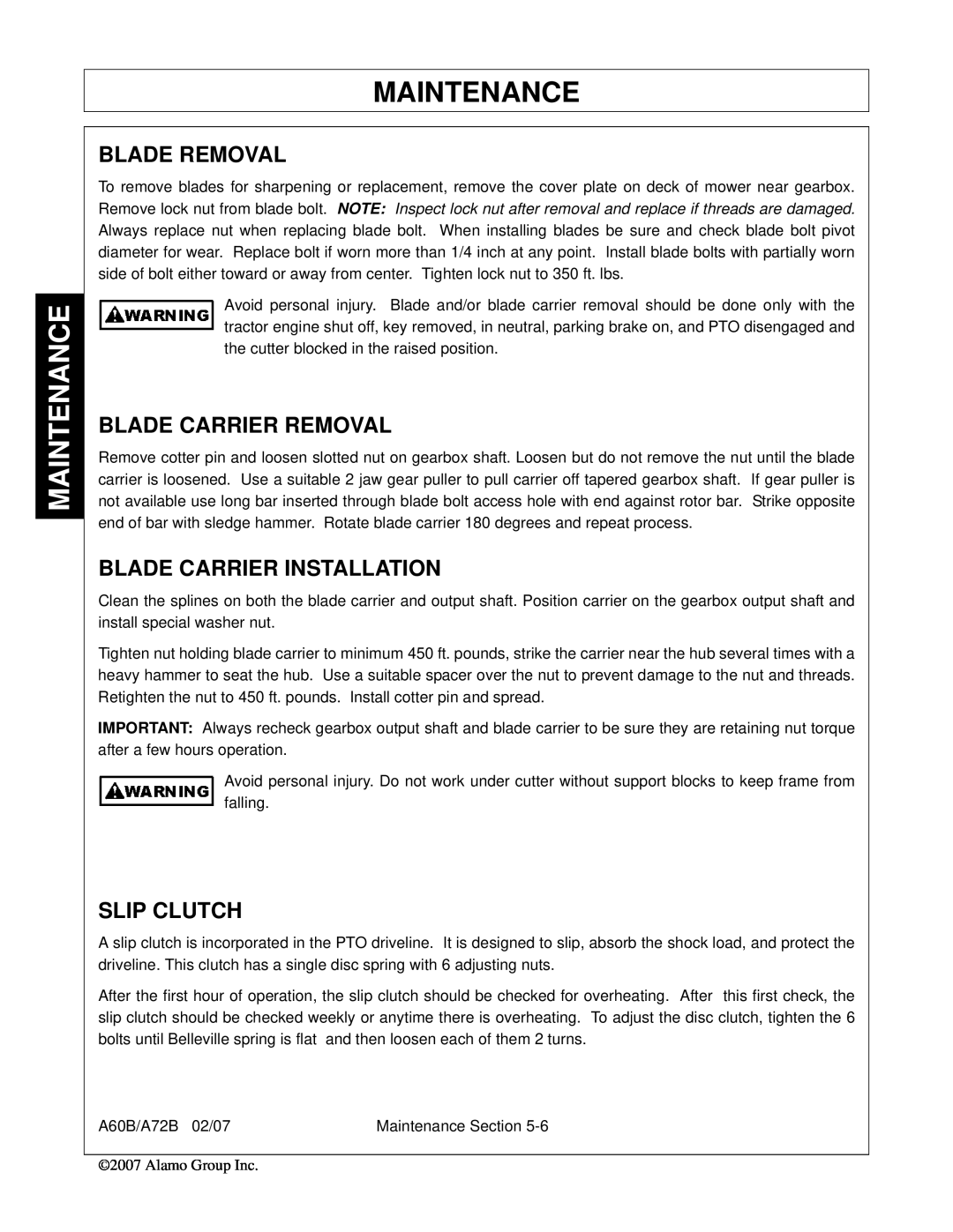
00759354C Blade Removal, Blade Carrier Removal, Blade Carrier Installation, Slip Clutch
Models:
00759354C
A72B
A60B
1
134
138
138
Download
138 pages
33.92 Kb
131
132
133
134
135
136
137
138
Troubleshooting
Install
Warranty
Maintenance
Assembly Section
Engagement Check Procedure
Setting The Mower
Weight
Safety
Power Take Off PTO
Page 134
Image 134
Page 133
Page 135
Page 134
Image 134
Page 133
Page 135
Contents
ALAMO INDUSTRIAL
A60B A72B
ROTARY MOWER
OPERATOR’S MANUAL
To the Owner/Operator/Dealer
ASSEMBLY SECTION
Table Of Contents
SAFETY SECTION
INTRODUCTION SECTION
MAINTENANCE SECTION
Page
one 1 AEM Mower Safety Practices Video
Alamo Industrial Division is willing to provide
SAFETY SECTION
Safety Section
General Safety Instructions and Practices
SAFETY
SAFETY
“Wait a minute...Save a life!”
SAFETY
Equipment Operation Safety Instructions and Practices
lines. S3PT-5
SFL-4
SAFETY
SAFETY
SAFETY
SAFETY
SAFETY
STOP MOWING IF PASSERSBY ARE WITHIN 100 YARDS UNLESS
Transporting Safety Instructions and Practices
MPH. STI-6
Maintenance and Service Safety Instructions and Practices
SG-5
SAFETY
SEE YOUR RHINO DEALER
Storage and Parking Safety Instructions and Practices
Concluding Safety Instructions and Practices
Decal Location
TYPE
DESCRIPTION
Decal Description
SAFETY
SAFETY
SAFETY
SAFETY
SAFETY
SAFETY
SAFETY
Employer Responsibilities
Federal Laws and Regulations
Employer-Employee Operator Regulations
Child Labor Under 16 Years of Age
Page
Page
Page
Page
Page
Page
Page
Page
Page
Page
Page
Page
Page
Page
Page
Page
Page
Page
Page
Page
Page
Page
Page
Page
Page
Page
Page
Page
Page
Page
Page
Page
Page
Page
Page
Page
Page
Page
Page
Page
Page
Page
Page
Page
Page
INTRODUCTION SECTION
Introduction Section
INTRODUCTION
INTRODUCTION
INTRODUCTION
Attention Owner/Operator
ASSEMBLY SECTION
Assembly Section
A-Frame Assembly
ASSEMBLY
ASSEMBLY
Optional Equipment at Extra Cost
Tailwheel Assembly
Front and Rear Deflectors Standard Equipment and Chain Guards
ASSEMBLY
Figure Asm-R-0085 Rear Rubber Fabric Deflectors Standard Equipment
Front Rubber Fabric Deflectors Standard Equipment
Front Deflector Figure Asm-R-0085
Rear Deflector Figure Asm-R-0086
Front Chain Guard - A60 & A72
Chainguards Optional Equipment at Extra Cost
Chainguards
Rear Chain Guards Optional Equipment
Driveline Attachment
SLIP CLUTCH SHIELD ASSEMBLY
Check Chains - Extra Equipment - for Lift-Models
Offset Adapter Hitch - Extra Equipment
OPERATION SECTION
Operation Section
A60B/A72B MEDIUM-DUTY ROTARY MOWER OPERATION INSTRUCTIONS
OPERATION
OPERATION
A72B
1. Standard Equipment and Specifications
A60B
2. OPERATOR REQUIREMENTS
PERSONAL PROTECTIVE EQUIPMENT PPE
Tractor Requirements and Capabilities
3.2 Tractor Safety Devices
3. TRACTOR REQUIREMENTS
3.1 ROPS and Seat Belt
3.4 3-Point Hitch
3.3 Tractor Horsepower
3.5 Front End Weight
CAT I Implement / Hitch Specification
3.6 Power Take Off PTO
4. GETTING ON AND OFF THE TRACTOR
4.1 Boarding the Tractor
4.2 Dismounting the Tractor
6. CONNECTING THE MOWER TO THE TRACTOR
5. STARTING THE TRACTOR
7. SETTING THE MOWER
7.1 Setting Mower Height
7.2 Setting Deck Pitch
8. DRIVELINE ATTACHMENT
9. Driveline Length Check
“Bottoming Out” Check Procedure
Shorten the driveline profiles as follows
10. PRE-OPERATION INSPECTION AND SERVICE
Engagement Check Procedure
10.1 Tractor Pre-Operation Inspection/Service
10.2 Mower Pre-Operation Inspection/Service
Mower ID#
Rotary Mower PRE-OPERATION Inspection
DO NOT OPERATE an UNSAFE TRACTOR or MOWER
Make
Tractor PRE-OPERATION Inspection
OPERATION
OPERATION
OPERATION
OPERATION
OPERATION
10.3 Cutting Component Inspection
OPS-U-0031
11. DRIVING THE TRACTOR AND IMPLEMENT
11.2 Brake and Differential Lock Setting
11.1 Starting the Tractor
11.3 Raising the Mower
11.4 Driving the Tractor and Mower
11.5 Crossing Ditches and Steep Inclines
12. OPERATING THE TRACTOR AND IMPLEMENT
12.2 Bystanders/Passersby Precautions
12.1 Foreign Debris Hazards
12.3 Engaging the Power Take Off PTO
12.4 PTO RPM and Ground Speed
12.5 Operating the Mower
OPERATION
OPERATION
OPERATION
OPERATION
OPERATION
13. DISCONNECTING THE MOWER FROM THE TRACTOR
12.6 Shutting Down the Implement
OPERATION
14. MOWER STORAGE
15. TRANSPORTING THE TRACTOR AND IMPLEMENT
15.1 Transporting on Public Roadways
OPERATION
15.2 Hauling the Tractor and Implement
OPERATION
Possible Cause
16. TROUBLESHOOTING GUIDE
Problem
Remedy
OPERATION
OPERATION
OPERATION
MAINTENANCE SECTION
Maintenance Section
Lubrication
MAINTENANCE
MAINTENANCE
Mnt-R-0087
DRIVELINE LUBRICATION
TAIL WHEEL ASSEMBLY
GEARBOX
BLADE SERVICING
BLADE SHARPENING
BLADE CARRIER REMOVAL
BLADE CARRIER INSTALLATION
BLADE REMOVAL
SLIP CLUTCH
SEASONAL CLUTCH MAINTENANCE
LIMITED WARRANTY
ALAMO-INDUSTRIAL
ALAMO INDUSTRIAL
Equip tractors with rollover protection ROPS and keep all machinery
TO THE OWNER/OPERATOR/DEALER
Keep children away from danger all day, every day
guards in place
Printed U.S.A
A60B/A72B- SOM- 02/07
P/N 00759354C
Top
Page
Image
Contents