ASSEMBLY

HYDRAULIC OR MANUAL LIFT

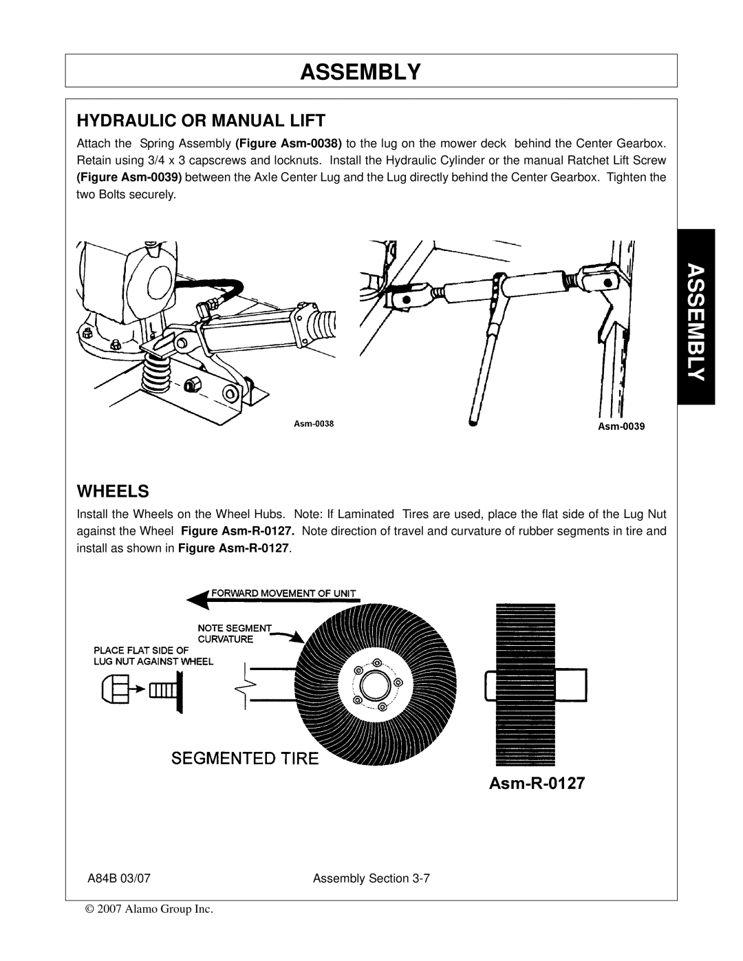
Attach the Spring Assembly (Figure Asm-0038)to the lug on the mower deck behind the Center Gearbox. Retain using 3/4 x 3 capscrews and locknuts. Install the Hydraulic Cylinder or the manual Ratchet Lift Screw (Figure Asm-0039)between the Axle Center Lug and the Lug directly behind the Center Gearbox. Tighten the two Bolts securely.

WHEELS

Install the Wheels on the Wheel Hubs. Note: If Laminated Tires are used, place the flat side of the Lug Nut against the Wheel Figure Asm-R-0127.Note direction of travel and curvature of rubber segments in tire and install as shown in Figure Asm-R-0127.

A84B 03/07

Assembly Section 3-7

© 2007 Alamo Group Inc.

ASSEMBLY

Page 85
Image 85
Alamo A84B manual Hydraulic or Manual Lift, Wheels