Guide to installation and operation |
| |
|
|
|
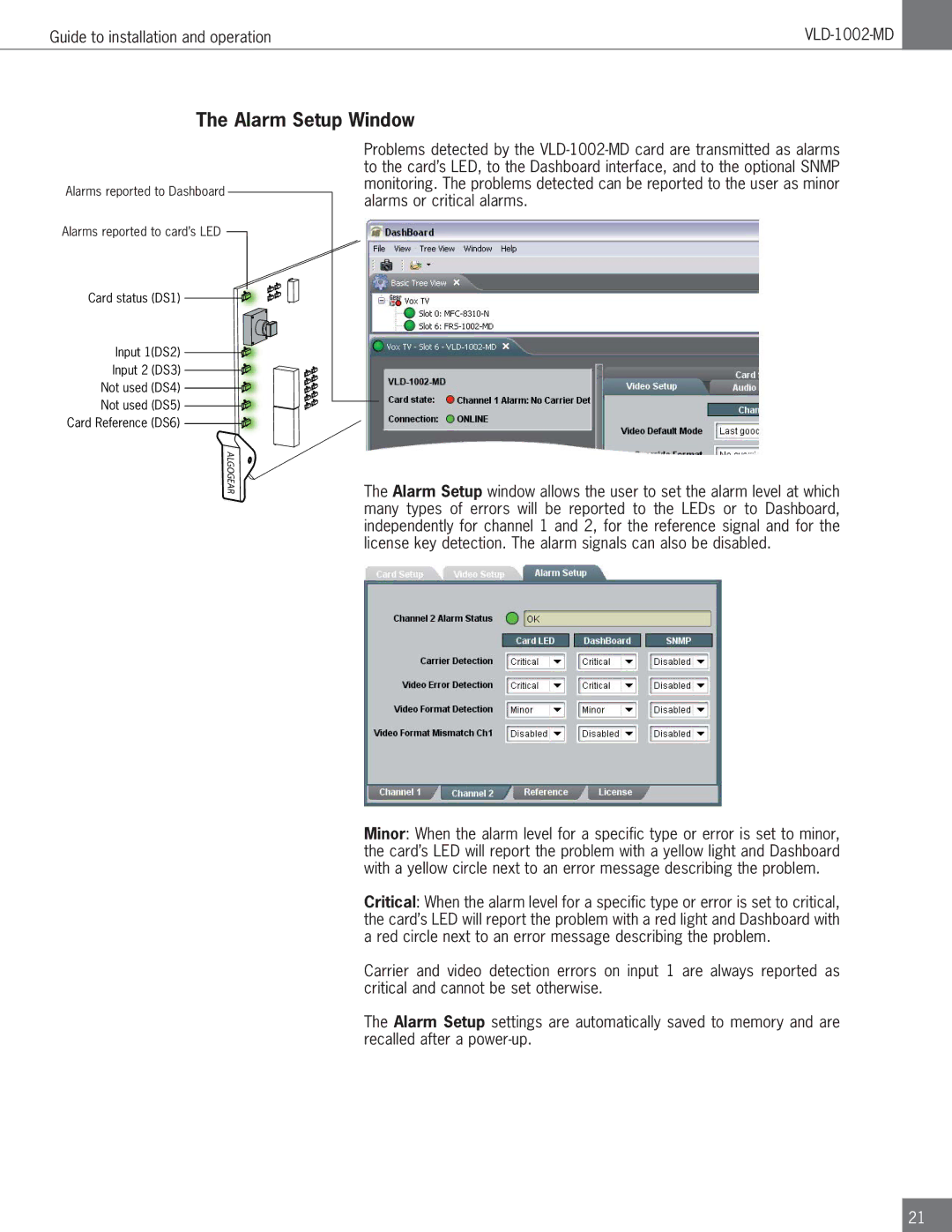
The Alarm Setup Window
Alarms reported to Dashboard
Alarms reported to card’s LED
Card status (DS1) 


Problems detected by the
Input 1(DS2)
Input 2 (DS3) Not used (DS4) Not used (DS5)
Card Reference (DS6)
![]() ALGOGEAR
ALGOGEAR ![]()
![]()

The Alarm Setup window allows the user to set the alarm level at which many types of errors will be reported to the LEDs or to Dashboard, independently for channel 1 and 2, for the reference signal and for the license key detection. The alarm signals can also be disabled.
Minor: When the alarm level for a specific type or error is set to minor, the card’s LED will report the problem with a yellow light and Dashboard with a yellow circle next to an error message describing the problem.
Critical: When the alarm level for a specific type or error is set to critical, the card’s LED will report the problem with a red light and Dashboard with a red circle next to an error message describing the problem.
Carrier and video detection errors on input 1 are always reported as critical and cannot be set otherwise.
The Alarm Setup settings are automatically saved to memory and are recalled after a
21