4AC16LT specifications
The Allied Air Enterprises 4AC16LT is a highly efficient air conditioning unit designed to provide optimal cooling solutions for residential and light commercial applications. This model exemplifies the balance of innovative technology and user-friendly features, making it a popular choice for homeowners and contractors alike.One of the standout characteristics of the 4AC16LT is its ENERGY STAR certification, which signifies its energy efficiency and eco-friendly operation. The unit is engineered to reduce energy consumption while delivering reliable performance, ultimately helping to lower electricity bills for consumers.
The 4AC16LT features a scroll compressor, a technology known for its durability and efficiency. This compressor design not only improves the overall cooling efficiency but also minimizes operational noise, providing a quiet and comfortable indoor environment. The unit's sound levels are notably reduced, making it ideal for residential settings where noise can be a significant concern.
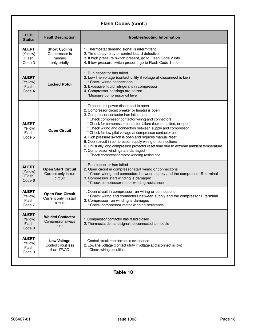
In addition to its efficient compressor, the unit boasts a range of advanced technologies. The integrated smart diagnostic features allow technicians to quickly identify and troubleshoot issues, streamlining maintenance and reducing downtime. This is particularly beneficial for contractors, as it enhances service response times and customer satisfaction.
The 4AC16LT is also equipped with a durable cabinet design, which is resistant to rust and corrosion, ensuring longevity and reliability in various environmental conditions. The pre-painted steel casing not only enhances the unit’s durability but also adds an aesthetic appeal that blends well with most home exteriors.
Further enhancing its appeal, the unit utilizes environmentally friendly refrigerants that comply with current regulations. This commitment to sustainability demonstrates Allied Air Enterprises’ focus on innovation while caring for the environment.
Moreover, the model is designed with ease of installation in mind. The compact size and lightweight construction of the 4AC16LT facilitate straightforward installation, saving time and labor costs for technicians.
In summary, the Allied Air Enterprises 4AC16LT air conditioning unit is a top-tier choice that incorporates energy efficiency, advanced technology, and a user-friendly design. Its combination of quiet operation, robust features, and commitment to sustainability makes it an excellent investment for anyone seeking reliable indoor comfort.