AT-FS750/24POE specifications
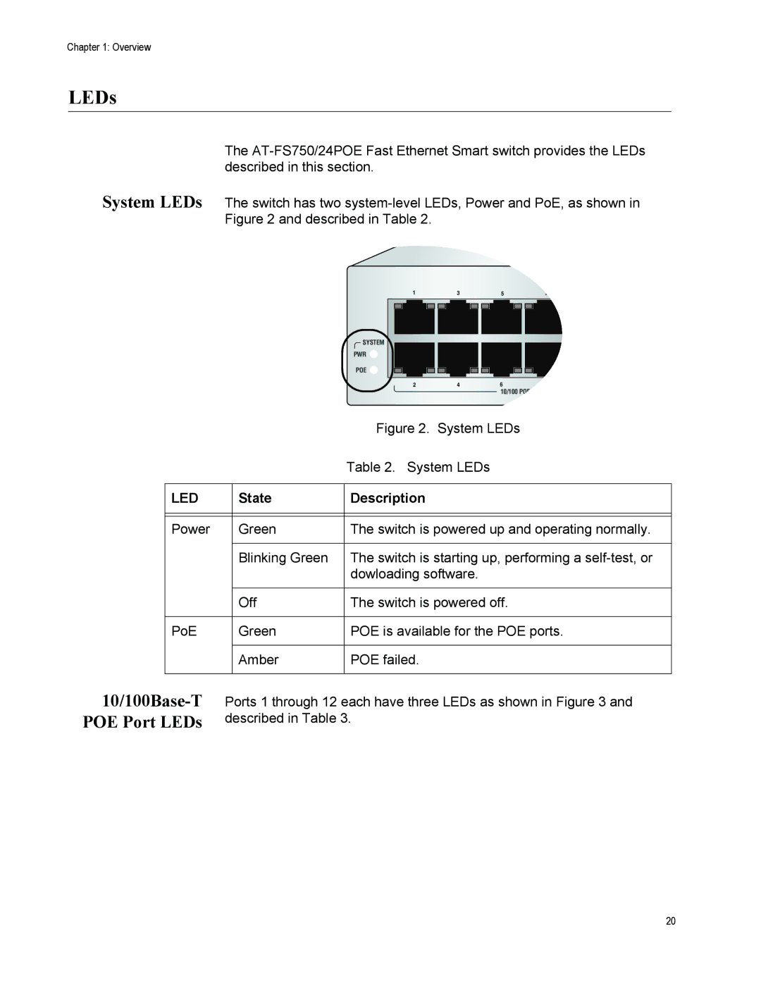
Allied Telesis is renowned for its high-quality networking solutions, and the AT-FS750 series exemplifies this commitment with its robust functionality and advanced features. The AT-FS750/24POE and AT-FS750/48 are two powerful models designed to meet the diverse needs of modern networks, providing reliable connectivity and efficient power management.The AT-FS750/24POE model is particularly notable for its Power over Ethernet (PoE) capabilities, allowing it to deliver power and data over the same Ethernet cable. This is especially beneficial for deploying devices like IP phones, security cameras, and wireless access points in locations where power sources may be limited. With 24 PoE-enabled ports, the switch can efficiently power multiple devices simultaneously, streamlining installations and reducing clutter.
Conversely, the AT-FS750/48 offers a more extensive configuration with 48 standard Ethernet ports. This model is ideal for larger networks that require seamless connectivity for a higher number of devices. Its robust architecture ensures optimal performance and reliability in demanding environments, making it a preferred choice for enterprises looking to enhance their infrastructure.
A key feature of both models is the Layer 2 switching technology, which ensures high-speed data forwarding and efficient traffic management within the local area network (LAN). This technology supports essential protocols such as VLAN (Virtual Local Area Network) tagging, enabling network segmentation and better security. The switches also boast a high switching capacity, ensuring minimal latency and maximizing throughput for connected devices.
Both AT-FS750 switches are designed with user-friendly management options. They support a web-based interface, simplifying configuration and monitoring tasks for IT staff. Additionally, the switches incorporate SNMP (Simple Network Management Protocol) for streamlined network management, allowing administrators to oversee network performance and troubleshoot issues effectively.
Another notable characteristic is their compact, fanless design, which not only reduces noise but also extends the lifespan of the equipment due to minimized thermal stress. The rugged casing ensures durability, making them suitable for various environments, from small offices to large enterprise networks.
In summary, the Allied Telesis AT-FS750/24POE and AT-FS750/48 switches provide a versatile solution for organizations seeking reliable and efficient networking capabilities. With PoE support, comprehensive management features, and robust performance, these switches are well-suited to meet the evolving demands of today's networking landscape.

