COMMERCIAL RECEIVER & TRANSMITTER CODING INSTRUCTIONS
The 831E receiver may be used with many different Allstar transmitters. The information below indicates how to set the coding | |||||
switches in the various transmitters and the 831E receiver. |
|
|
|
| |
IF | YOU ARE USING A 8831 | 831 STANDARD | TRANSMITTER | RECEIVER |
|
TRANSMITTER: |
|
| Coding Switch |
| |
| Switch Position | #6 |
| ||
Exactly match all 8 code switches in the transmitter and receiver. The code switches |
| ||||
|
|
| |||
A | + |
| |||
may be set in any random pattern of +, - and 0. |
|
| |||
IF | YOU ARE USING A 8831C | 733 STANDARD | B | 0 |
|
TRANSMITTER: |
| C | - |
| |
These transmitters are used to control up to 3 different doors. This is accomplished by setting the selector switch on the transmitter to either A, B & C and setting the #6 coding switch in the 831E receiver .
Start coding by exactly matching all 8 code switches in the transmitter and the receivers. The code switches may be set in any random pattern of +, 0 and - positions. Next, in receiver A, set code switch #6 to the + position; In receiver B set code switch # 6 to the 0 position; In receiver C set code switch # 6 to the - position. The table to the right shows the switch positions.
IF YOU ARE USING A 639 STANDARD TRANSMITTER:
This transmitter is used to control up to 9 different doors. This is accomplished by setting the selector switch on the transmitter to either 1, 2, 3, 4, 5, 6, 7, 8 or 9 and setting the #7 and #8 coding switches in the 831E receiver.
Start coding by exactly matching all 8 code switches in the transmitter and receivers. The code switches may be set in any random pattern of +, 0 and - positions. Next, in receiver 1, set code switch #7 to + and code switch #8 +; In receiver 2, set code switch #7 to + and code switch #8 to 0. Continue setting the codes in the 831E receivers as shown in the table.
IF YOU ARE USING A 53S STANDARD TRANSMITTER:
This transmitter is used to control up to 27 different doors. This is accomplished by setting the selector switches to either A, B or C and either 1, 2, 3, 4, 5, 6, 7, 8 or 9 and setting the #6, #7 and #8 coding switches in the 831E receiver.
TRANSMITTER |
|
|
1 - 9 Selector | 831 RECEIVER | 831 RECEIVER |
Switch Position | Code Switch #7 | Code Switch #8 |
1 | + | + |
2 | + | 0 |
3 | + | - |
4 | 0 | + |
5 | 0 | 0 |
6 | 0 | - |
7 | - | + |
8 | - | 0 |
9 | - | - |
Start coding by exactly matching all 8 code switches in the transmitter and receiver. Next, in receiver A1, set code switch #6 to +, set code switch #7 to + and code switch #8 to +; In receiver A2, set code switch #6 to +, set code switch #7 to + and code switch #8 to 0. Continue setting the codes in the 831E receivers, using both tables shown above.
MASTER/SLAVE WIRING INSTRUCTIONS
Master/Slave systems are recommended for installations in which | 105114 |
|
| DATA |
|
|
|
|
|
|
| |
receivers must be mounted less than ten feet apart. When two or more |
| DATA COMMON |
|
|
|
|
|
|
| |||
|
|
|
|
|
|
|
|
| ||||
receivers are mounted close together there is a potential for receiver |
|
|
|
|
|
|
|
|
| |||
|
|
|
|
|
|
|
|
|
|
|
| |
|
|
|
|
|
|
|
|
|
|
|
| |
function poorly (or not at all). In Master/Slave systems, the Master |
|
|
|
|
|
|
|
|
|
|
|
|
receiver accepts the transmitted signal and passes it to the Slave |
|
|
|
|
|
|
|
|
|
|
|
|
receivers through a pair of wires connecting the receivers. The RF |
|
|
|
|
|
|
|
|
|
|
|
|
section of the Slave receivers are disabled to prevent |
|
|
|
|
|
|
|
|
|
|
|
|
|
|
|
|
|
|
|
|
|
|
|
| |
|
|
|
|
|
|
|
|
|
|
|
| |
to 15 Slave receivers may be connected to a Master receiver. Master/ | MASTER |
|
|
| SLAVE #1 |
|
|
| SLAVE #2 |
|
|
|
Slave units are specially ordered from the Factory. |
|
|
|
|
|
|
|
|
|
|
|
|
|
|
|
|
|
|
|
|
|
|
|
| |
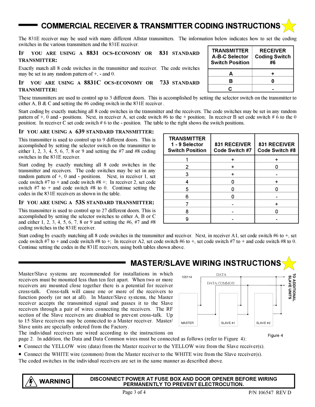
The individual receivers are wired according to the instructions on
page 2. In addition, the Data and Data Common wires must be connected as follows (refer to Figurez4):
•Connect the YELLOW wire (data) from the Master receiver to the YELLOW wire from the Slave receiver(s).
•Connect the WHITE wire (common) from the Master receiver to the WHITE wire from the Slave receiver(s). The coded switches in the individual receivers are set in the same manner as described above.
TO ADDITIONAL SLAVE UNITS
WARNING | DISCONNECT POWER AT FUSE BOX AND DOOR OPENER BEFORE WIRING | |
PERMANENTLY TO PREVENT ELECTROCUTION. | ||
|
Page 3 of 4 | P/N 106547 REV D |