Installation
Metal plate
Detachable
Front panel
Caution
When you install this unit in your car, do not remove the detachable front panel.
If the detachable front panel is removed during installation, you might press too hard and warp the metal plate that holds it in place.
Caution
Do not block the unit’s fan or heat sink, thus preventing air circulation. If blocked, heat will accumulate inside the unit and may cause a fire.
Air ventilation hole |
| Air ventilation hole | |||||||||||||||
|
|
|
|
|
|
|
|
|
|
|
|
|
|
|
|
|
|
|
|
|
|
|
|
|
|
|
|
|
|
|
|
|
|
|
|
|
|
|
|
|
|
|
|
|
|
|
|
|
|
|
|
|
|
(Rear of | (Rear of |
1
Mounting Sleeve (Included)
Dashboard
this unit
Slide the mounting sleeve into the dashboard.
Connect each input lead coming from an amplifier or equalizer to the corresponding output lead coming from the left rear of the
3
Lock Pin
Slide the
Removal
1Remove the detachable front panel.
2Use a small screwdriver (or similar tool) to push the locking pins to the “up” position (see above drawing). As each pin is unlocked, gently pull out on the unit to make sure it does not
3Pull the unit out, keeping it unlocked as you do so.
<JAPANESE CAR>
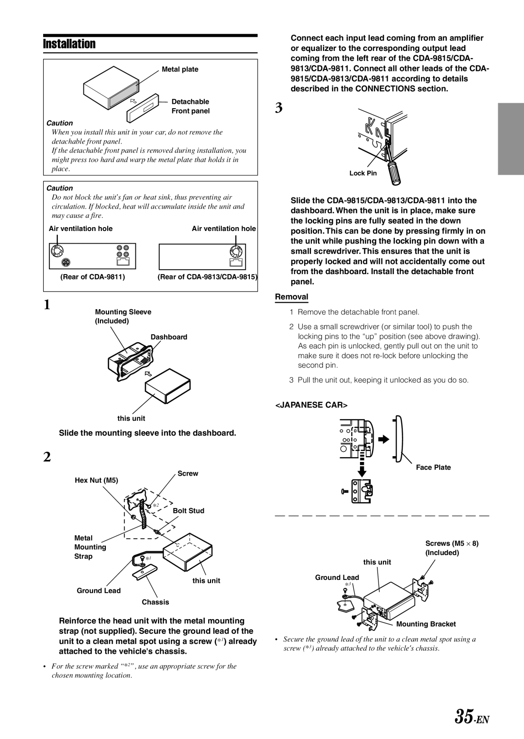
2
Hex Nut (M5)
*2
Metal
Mounting
Strap![]() *1
*1
Ground Lead
Screw
Bolt Stud
this unit
Face Plate
Screws (M5 ⋅ 8) (Included)
this unit
Ground Lead
*3 ![]()
Chassis
Reinforce the head unit with the metal mounting strap (not supplied). Secure the ground lead of the unit to a clean metal spot using a screw (*1) already attached to the vehicle's chassis.
•For the screw marked “*2”, use an appropriate screw for the chosen mounting location.
Mounting Bracket
•Secure the ground lead of the unit to a clean metal spot using a screw (*3) already attached to the vehicle's chassis.