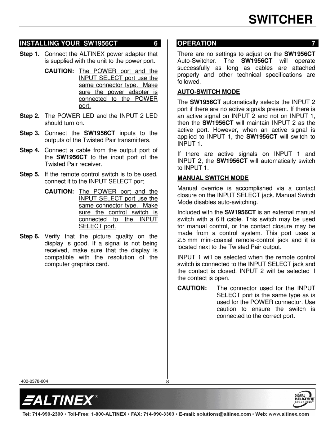
SW1956CT specifications
The Altinex SW1956CT is a cutting-edge multimedia switcher designed to streamline and enhance audio-visual presentations in a variety of settings. With a focus on flexibility and efficiency, the SW1956CT is ideal for conference rooms, auditoriums, and educational environments where reliable connectivity is essential.One of the standout features of the SW1956CT is its capability to switch between multiple input sources. It supports an impressive array of connections, including HDMI, VGA, and audio inputs, enabling seamless integration of various devices such as laptops, projectors, and sound systems. This versatility ensures that users can easily connect different equipment without the hassle of constant reconfiguration.
The technology behind the SW1956CT is designed to deliver high-quality video and audio output. It supports resolutions up to 1920x1080 at 60Hz, ensuring crisp and clear visual presentations. Additionally, the switcher employs advanced scaling capabilities, automatically adjusting the output resolution to match that of the display device. This feature is particularly useful in mixed environments where devices with different output resolutions are used.
Another significant characteristic of the SW1956CT is its user-friendly interface. It comes equipped with an intuitive control system that allows for easy switching between inputs, making it accessible for users of all technical skill levels. The front-panel controls provide quick access to essential functions, while optional remote control and RS-232 connectivity offer additional convenience for advanced users.
In terms of build quality, the Altinex SW1956CT is constructed with durability in mind. The rugged design ensures it can withstand the demands of frequent use in commercial environments. Furthermore, it includes built-in cooling solutions to manage heat dissipation, thereby extending the device's lifespan and maintaining optimal performance.
In conclusion, the Altinex SW1956CT stands out as a versatile and highly capable multimedia switcher. Its ability to handle multiple input formats, deliver high-resolution output, and provide a user-friendly interface makes it a valuable tool for any audio-visual setup. Whether for corporate presentations or educational purposes, the SW1956CT ensures a hassle-free and engaging user experience. With its robust design and advanced technology, it is a reliable choice for professionals seeking a high-performance switching solution.

