|
| DESIGNER SOLUTIONS |
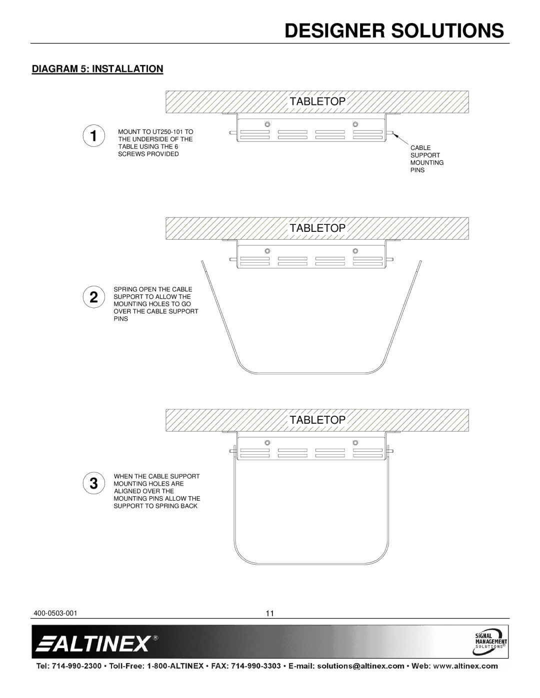
DIAGRAM 5: INSTALLATION |
| |
|
| TABLETOP |
1 | MOUNT TO |
|
THE UNDERSIDE OF THE |
| |
| TABLE USING THE 6 | CABLE |
| SCREWS PROVIDED | SUPPORT |
MOUNTING
PINS
![]()
![]()
![]() TABLETOP
TABLETOP![]()
![]()
SPRING OPEN THE CABLE
2 SUPPORT TO ALLOW THE MOUNTING HOLES TO GO OVER THE CABLE SUPPORT PINS


 TABLETOP


WHEN THE CABLE SUPPORT
3 MOUNTING HOLES ARE ALIGNED OVER THE MOUNTING PINS ALLOW THE SUPPORT TO SPRING BACK
11 |