Manuals
/
Altinex
/
Computer Equipment
/
Switch
Altinex
UT250-101
manual
Diagram 4 Cable Support
Models:
UT250-101
1
11
22
22
Download
22 pages
45.92 Kb
8
9
10
11
12
13
14
15
Troubleshooting
Specifications
Install
Application Diagrams
Description of Commands
Cleaning
AUTO-SWITCH Mode
Page 11
Image 11
DESIGNER SOLUTIONS
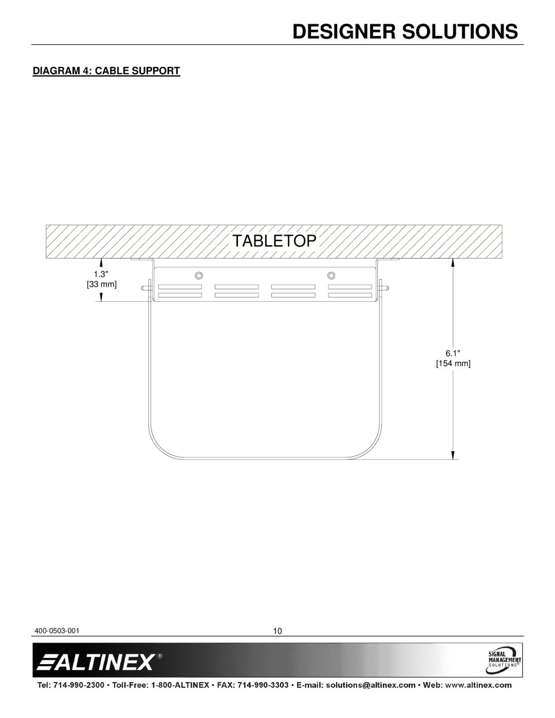
DIAGRAM 4: CABLE SUPPORT
TABLETOP
1.3" [33 mm]
6.1" [154 mm]
400-0503-001
10
Page 10
Page 12
Page 11
Image 11
Page 10
Page 12
Contents
UT250-101
Table of Contents
Handling
Precautions / Safety Warnings
Cleaning
General
About Your UT250-101
UT250-101
Specifications are subject to change
Technical Specifications
Mechanical
Product Description
Diagram 1 Typical Setup
Application Diagrams
Diagram 2 Internal View
Diagram 3 Dimensions
Diagram 4 Cable Support
Tabletop
Diagram 5 Installation
Diagram 6 Output Select Wiring
Manual Control Output Select Controls
Installing Your UT250-101
AUTO-SWITCH Mode
Operation
Status
Description of Commands
RS-232 Control
1 RS-232 Interface
OFFmX
CLR
VER
ONmX
Auto
InO
10. …P
11. SW
STA0
Help
17. ?
STA1
RSI
20. ...S
AFB
SIDn
Troubleshooting Guide
No Twisted Pair Output
No Response
Contact Information ALTINEX, Inc
Limited WARRANTY/RETURN Policies
Altinex Policies
Top
Page
Image
Contents