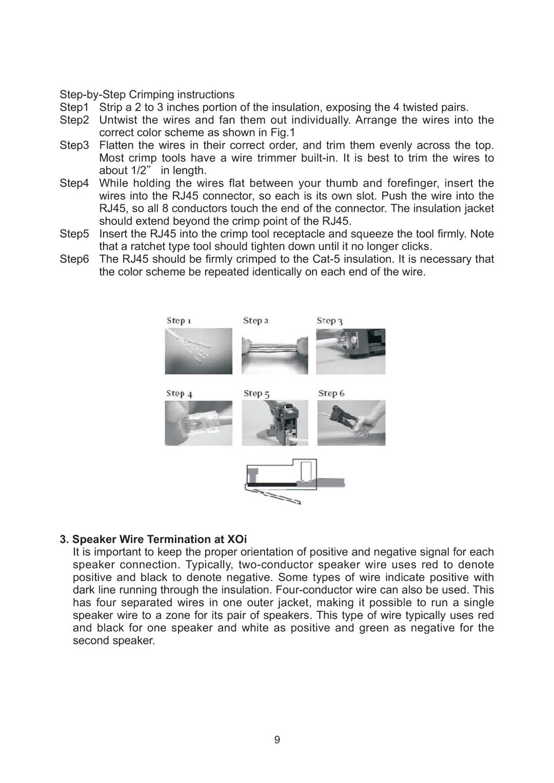
Step1 | Strip a 2 to 3 inches portion of the insulation, exposing the 4 twisted pairs. |
Step2 | Untwist the wires and fan them out individually. Arrange the wires into the |
| correct color scheme as shown in Fig.1 |
Step3 | Flatten the wires in their correct order, and trim them evenly across the top. |
| Most crimp tools have a wire trimmer |
| about 1/2 in length. |
Step4 | While holding the wires flat between your thumb and forefinger, insert the |
| wires into the RJ45 connector, so each is its own slot. Push the wire into the |
| RJ45, so all 8 conductors touch the end of the connector. The insulation jacket |
| should extend beyond the crimp point of the RJ45. |
Step5 | Insert the RJ45 into the crimp tool receptacle and squeeze the tool firmly. Note |
| that a ratchet type tool should tighten down until it no longer clicks. |
Step6 | The RJ45 should be firmly crimped to the |
| the color scheme be repeated identically on each end of the wire. |
3.Speaker Wire Termination at XOi
It is important to keep the proper orientation of positive and negative signal for each speaker connection. Typically,
9