Contents
Harmful interference To radio
FCC Compliance Statement
Declaration of Conformity
7ZXR
Page
How This Manual Is Organized
Bios
Page
Table Of Content
Revision History
Item Checklist
CPU
Summary Of Features
Bios
7ZXR
7ZXR Motherboard Layout
7ZXR Motherboard Layout
0AMD CPU Heat Sink Installation
CPU Speed Setup
Ë100 102 104 106 108 110 112 133
Set System Bus Speed
Connectors
Floppy Port Game & Audio Port
IDE1,IDE2 Primary/Secondary,IDE3/IDE4Raid/ATA100 Port
CPU Fan
J12 Wake On LAN
J15 Auxin
J18 CD Audio Line
JP8 / LED1 STR LED Connector & Dimm LED
USB 1 Connector
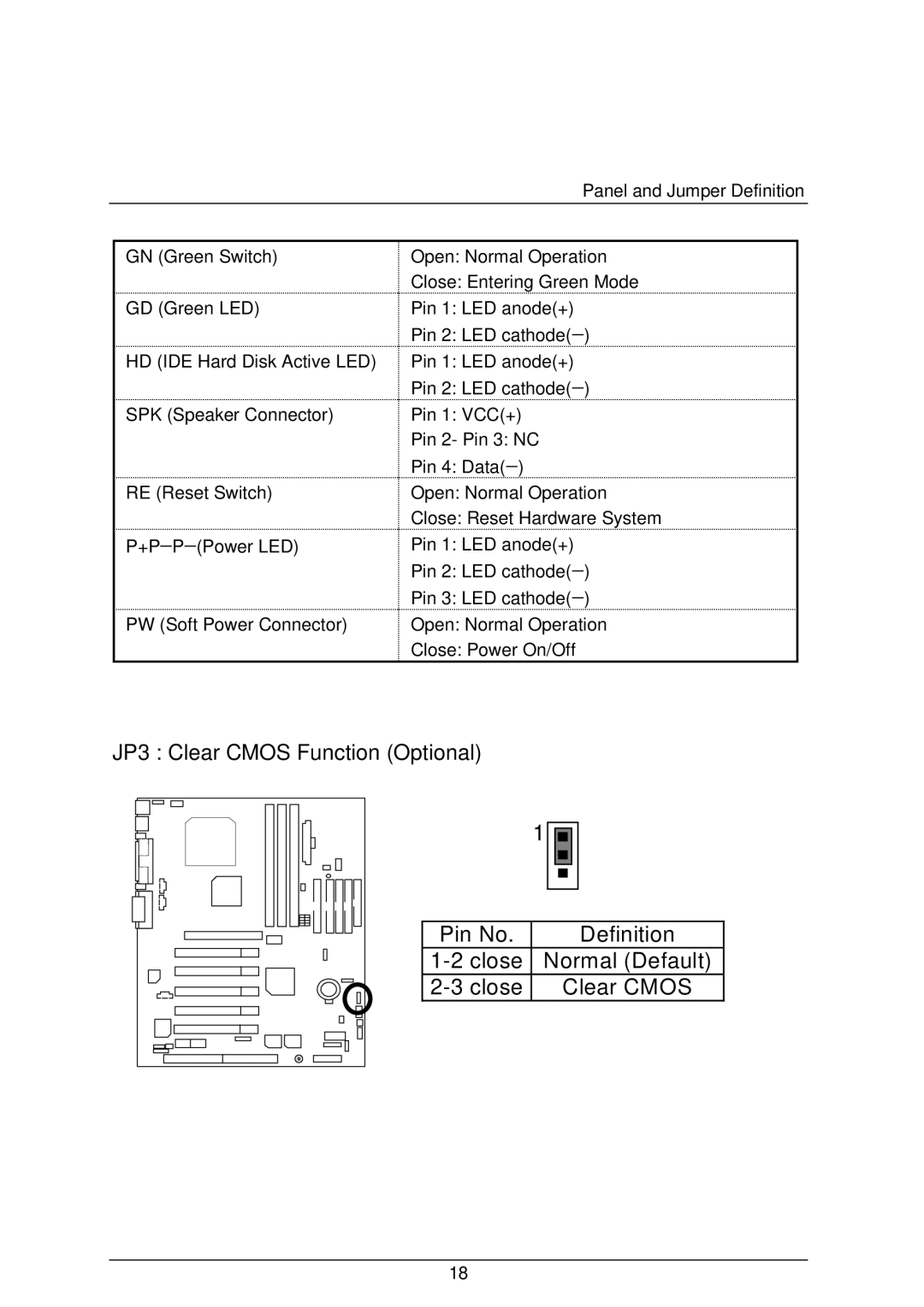
Panel And Jumper Definition
BAT1 Battery
JP3 Clear Cmos Function Optional
JP4 Rear USB Device Wake up Selection USB Connector Æ USB1
JP10 Bios Write Protection Optional
JP11 Front USB Device Wake up Selection USB Port Æ USB2
JP19 Onboard Promise Selection Optional
Winbench99
Performance List
Winstone99
AMD-K7TM
Block Diagram
STR function Installation
Suspend To RAM Installation
Step-By-Step Setup
Setup with Windows 98 CD
Step
How to put your system into STR mode?
Suspend to RAM Installation
How to recover from the STR sleep mode?
+ Dimm LED
Press F1 to enter Dual Bios Utility
Dual Bios Introduction
What is Dual Bios Technology?
How to use Dual BIOS? a. Boot Screen
Status
Bios will auto detect
Auto Recovery EnabledDefault, Disabled
Boot From Main Bios Default, Backup Bios
Halt On Error DisableDefault, Enable
Copy Main ROM Data to Backup
What’s DualBIOSTM?
DualBIOSTM Technology FAQ
What is DualBIOSTM technology? Answer
IV. Q Who Needs DualBIOSTM technology? Answer
III. Q How does DualBIOSTM technology work? Answer
7ZXR Motherboard
How to use Four Speaker?
What is Four Speaker?
Four Speaker & Spdif Introduction
Four Speaker Introduction
Four Speaker Application
What is SPDIF?
How to use SPDIF?
Spdif Introduction
7ZXR Motherboard
Four Speaker & Spdif Introduction
Gigabyte announces @ Bios Windows Bios live update utility
@ Bios Introduction
Gigabyte announces EasyTuneIII Windows overdrive utility
Easy TuneIIITM Introduction
7ZXR Motherboard
Raid Introduction
What is Raid?
RAID 0 stripe
RAID 1 mirror
Striping RAID
About RAID Levels
RAID 1 Mirroring
Mirroring RAID
Creating Your Disk Array
Creating a Security Array With New Drives
Creating an Array for Performance
Creating a Security Array With An Existing Data Drive
Raid Introduction
Viewing Bios Screen
Using FastBuild Configuration Utility
Using the Main Menu
Navigating the FastBuild Setup Menu
Optimize Array For
Creating Arrays Automatically
Defining Typical Application Usage
Using a Hot Spare Drive
Creating Multiple Disk Arrays
Mode
Viewing Drive Assignments
Manually Creating an Array
Array No RAID Mode Total Drv CapacityMB Status
Selecting Stripe Block
Selecting Array Type
Assigning Drives to Array
Adding Fault Tolerance to an Existing Drive
Creating a Mirrored Array Using New Drives
↑ Up ↓ ESC Exit Ctrl-Y Save
Making a Disk Array Bootable
How Saves Array Information
How Orders Arrays
Deleting An Array
7ZXR Motherboard
Rebuilding a Mirrored Array
Keys Available ↑ Up ↓ Down ESC Exit Enter Select
Halting Bios On Bootup Errors
Viewing Controller Settings
Viewing System Resources
Memory Installation
Bios Setup
Entering Setup
Bios Setup
Bios Features Setup
Standard Cmos Setup
Chipset Features Setup
Main Menu
PnP/PCI Configurations
Power Management Setup
Load Bios Defaults
Load Setup Defaults
Date
Standard Cmos Setup
Primary Master / Slave , Secondary Master / Slave
Time
Floppy Drive a / Drive B
Memory
Boot Sector Virus Protection
Base Memory
Extended Memory
1st / 2nd / 3rd Boot Device
Bios Features Setup
Password Check
Boot Up Num-Lock
Default value
A.R.T. for Hard Disks
Top Performance
Chipset Features Setup
Dram Frequency
Sdram CAS# Latency
PCI Delay Transaction
AGP Mode
AGP Comp. Driving
AGP Aperture Size
Delay Dram Read Latch
Bios Flash Protection
Sdram Command Drive
Dram Drive Strength
RAS# Drive
CAS# Drive
Acpi Sleep Type
Power Management Setup
USB Dev Wakeup From S3-S5
Suspend Time Out Minute
Soft-off by Power Button
Display Activity
System after AC Back Function
Resume On RTC Alarm
PnP OS Installed
PnP/PCI Configurations
Reset Configuration Data
VGA Boot From
IRQ 3,4,5,7,9,10,11,14,15
DMA Channel 0,1,3,5,6,7
Load Bios Defaults Y/N? N
Load Bios Defaults
Load Setup Defaults
Load Setup Defaults
On Board Serial Port a
Integrated Peripherals
On Board Serial Port B
Duplex Mode
Serial Port B Mode
Parallel Port Mode
On Board Parallel port
MC97 Modem
AC97 Audio
OnBoard Legacy Audio
Sound Blaster
Game Port 200h-207h
MPU-401 I/O Address
Hardware Monitor
Load Setup Defaults Exit Without Saving
Set Supervisor / User Password
IDE HDD Auto Detection
Save to Cmos and EXITY/N? Y
Save & Exit Setup
Quit without saving Y/N ? N
Exit Without Saving
Appendix
Click Next Click Finish to restart computer
Appendix B Creative Sound Driver Installation
Click here ClickNext Click Finish to restart computer
103
104
FastTrak Utility Installation
Click Next Click Finish to restart
Promise RAID Driver Installation
Bios update procedure
Appendix D Bios Flash Procedure
109
Aflashxxx.exe 7ZXR.f1 �
DDR
Appendix E Acronyms
VID

