3)3-Phase (3ø) Wiring Connections/Hookup “Reversing Models Only”
The electrical connections on ALL 3-phase (3ø) gas and steam dryers are made into the rear service box located at the upper left area of the dryer. Electrical connections for electrically heated dryers are made in the electric oven area located at the upper rear area of the dryer.
IMPORTANT: A separate circuit servicing each dryer must be provided.
If local codes permit, power to a gas or steam dryer can be made by the use of a flexible U.L. listed power cord/pigtail (wire size must conform to rating of dryer), or the dryer can be hard wired directly to the service breaker panel. In ALL cases, a strain relief must be installed where the wiring enters the dryer.
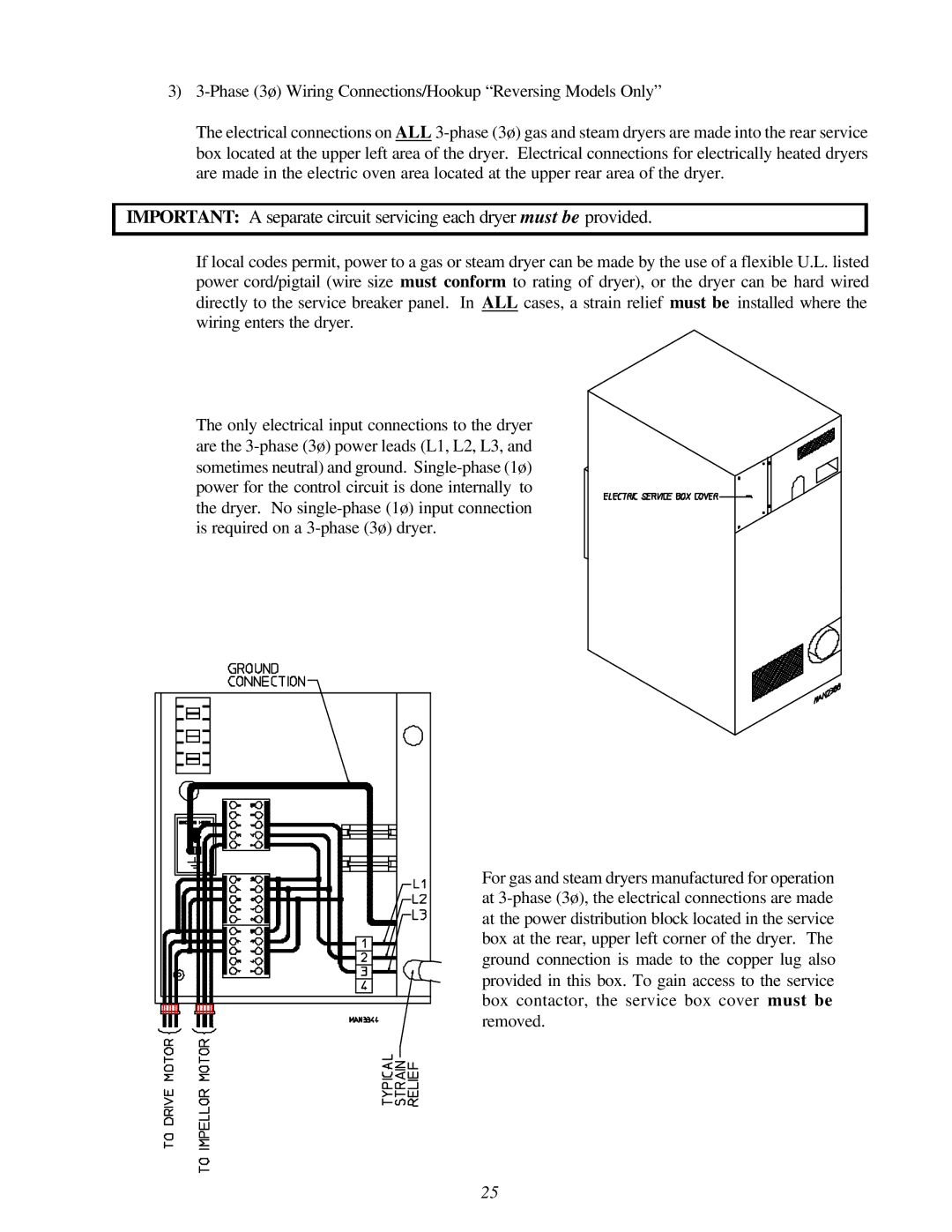
The only electrical input connections to the dryer are the 3-phase (3ø) power leads (L1, L2, L3, and sometimes neutral) and ground. Single-phase (1ø) power for the control circuit is done internally to the dryer. No single-phase (1ø) input connection is required on a 3-phase (3ø) dryer.
For gas and steam dryers manufactured for operation at 3-phase (3ø), the electrical connections are made at the power distribution block located in the service box at the rear, upper left corner of the dryer. The ground connection is made to the copper lug also provided in this box. To gain access to the service box contactor, the service box cover must be removed.