B. UNPACKING/SETTING UP
Remove protective shipping material (i.e., plastic wrap and/or optional shipping box) from dryer.
IMPORTANT: Dryer must be transported and handled in an upright position at ALL times.
The dryer can be moved to its final location while still attached to the skid or with the skid removed. To
1.Leveling Dryer
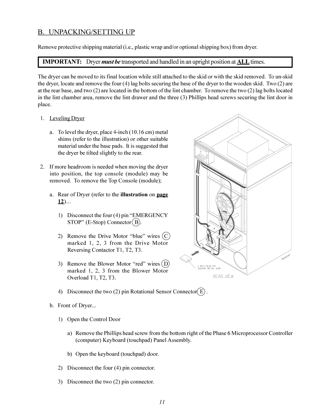
a.To level the dryer, place
2. If more headroom is needed when moving the dryer into position, the top console (module) may be removed. To remove the Top Console (module);
a. Rear of Dryer (refer to the illustration on page
12)...
1) Disconnect the four (4) pin “EMERGENCY STOP”
2) Remove the Drive Motor “blue” wires C marked 1, 2, 3 from the Drive Motor Reversing Contactor T1, T2, T3.
3)Remove the Blower Motor “red” wires D marked 1, 2, 3 from the Blower Motor Overload T1, T2, T3.
4)Disconnect the two (2) pin Rotational Sensor Connector E . b. Front of Dryer...
1)Open the Control Door
a)Remove the Phillips head screw from the bottom right of the Phase 6 Microprocessor Controller (computer) Keyboard (touchpad) Panel Assembly.
b)Open the keyboard (touchpad) door.
2)Disconnect the four (4) pin connector.
3)Disconnect the two (2) pin connector.
11