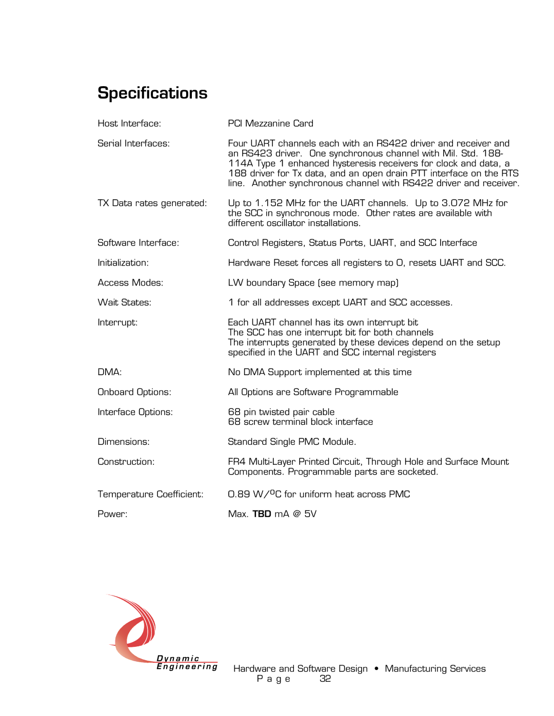
PMC-4U-CACI specifications
The American Dynamics PMC-4U-CACI is an advanced video management system designed for large-scale security operations, capable of handling extensive surveillance requirements across various industries, including transportation, education, retail, and urban security. With a focus on reliability, flexibility, and user-friendly design, the PMC-4U-CACI stands out as a robust solution for enhanced situational awareness and incident response.One of the main features of the PMC-4U-CACI is its support for both analog and digital cameras, providing flexibility for organizations upgrading their systems. This hybrid capability ensures that users can maintain their existing infrastructure while integrating new technologies. The system supports high-definition video resolutions, enabling crystal-clear image quality crucial for identifying details in critical situations.
The PMC-4U-CACI is equipped with an intuitive user interface that allows operators to navigate the system effortlessly. This design minimizes the learning curve, enabling security personnel to respond quickly to incidents. The interface also provides customizable views, allowing users to prioritize the most relevant camera feeds and data based on their operational needs.
Another significant characteristic of the PMC-4U-CACI is its scalability. It is engineered to support a vast number of cameras and can be expanded according to the growing needs of an organization. This adaptability makes it ideal for both small installations and large, multi-site deployments.
In terms of technologies, the PMC-4U-CACI incorporates advanced video analytics capabilities. These features include motion detection, line crossing alerts, and occupancy counting, all of which enhance the system’s ability to detect potential security breaches and optimize resources. Additionally, the system seamlessly integrates with various alarm and access control systems, creating a unified security solution.
Furthermore, the PMC-4U-CACI emphasizes data security and redundancy. The architecture is designed to ensure that video footage is securely stored and transmitted, protecting against unauthorized access. Built-in failover capabilities maintain system functionality during power outages or system failures, ensuring continuous surveillance.
In summary, the American Dynamics PMC-4U-CACI is a versatile and powerful video management system tailored for contemporary security challenges. Its hybrid capability for camera integration, user-friendly interface, scalability, advanced analytics, and robust security features make it an excellent choice for organizations seeking to bolster their surveillance and operational efficiency.

