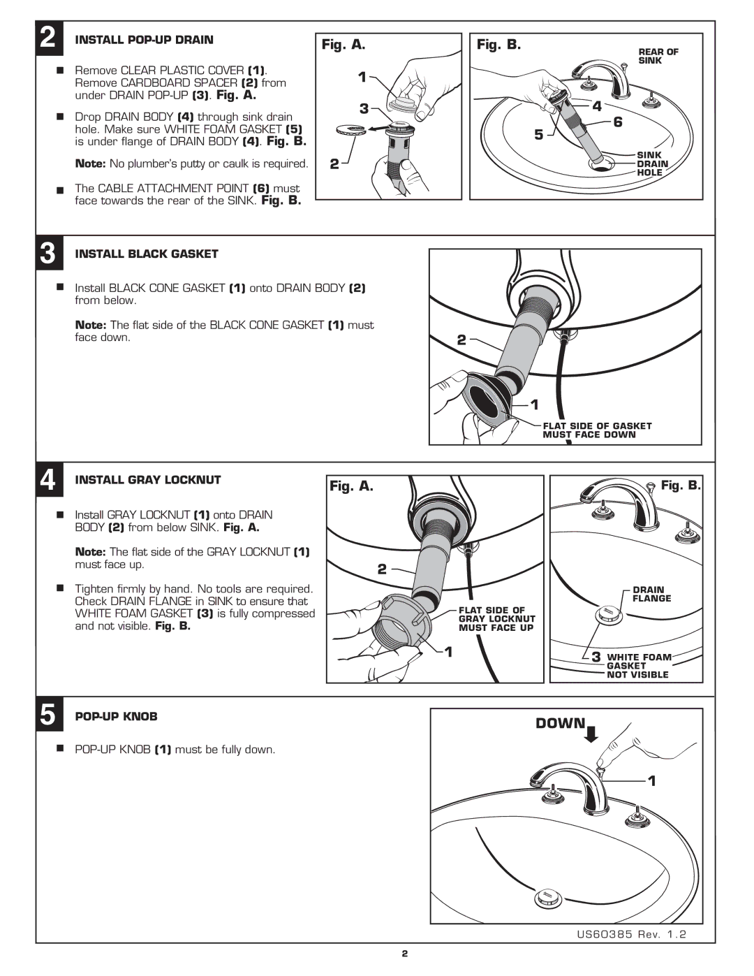
2 INSTALL POP-UP DRAIN
Remove CLEAR PLASTIC COVER (1). Remove CARDBOARD SPACER (2) from under DRAIN
Drop DRAIN BODY (4) through sink drain hole. Make sure WHITE FOAM GASKET (5) is under flange of DRAIN BODY (4). Fig. B.
Note: No plumber’s putty or caulk is required.
The CABLE ATTACHMENT POINT (6) must face towards the rear of the SINK. Fig. B.
Fig. A.
1![]()
![]()
3![]()
![]()
2![]()
Fig. B.
REAR OF
SINK
![]()
![]()
![]() 4
4
6
5
SINK
DRAIN
HOLE
3 INSTALL BLACK GASKET
Install BLACK CONE GASKET (1) onto DRAIN BODY (2) from below.
Note: The flat side of the BLACK CONE GASKET (1) must face down.
2
1
![]() FLAT SIDE OF GASKET MUST FACE DOWN
FLAT SIDE OF GASKET MUST FACE DOWN
4 | INSTALL GRAY LOCKNUT | Fig. A. |
| Fig. B. |
| Install GRAY LOCKNUT (1) onto DRAIN |
|
|
|
| BODY (2) from below SINK. Fig. A. |
|
|
|
| Note: The flat side of the GRAY LOCKNUT (1) |
|
|
|
| must face up. |
| 2 |
|
| Tighten firmly by hand. No tools are required. |
|
| DRAIN |
| Check DRAIN FLANGE in SINK to ensure that |
|
| FLANGE |
| WHITE FOAM GASKET (3) is fully compressed |
|
| FLAT SIDE OF |
| and not visible. Fig. B. |
|
| GRAY LOCKNUT |
|
|
| MUST FACE UP | |
|
|
| 1 | 3 WHITE FOAM |
|
|
|
| |
|
|
|
| GASKET |
|
|
|
| NOT VISIBLE |
5 |
|
|
| DOWN |
|
|
|
| |
|
|
|
| 1 |
US60385 Rev. 1 . 2
2