ELECTRICAL INSTALLATION
1ELECTRICAL
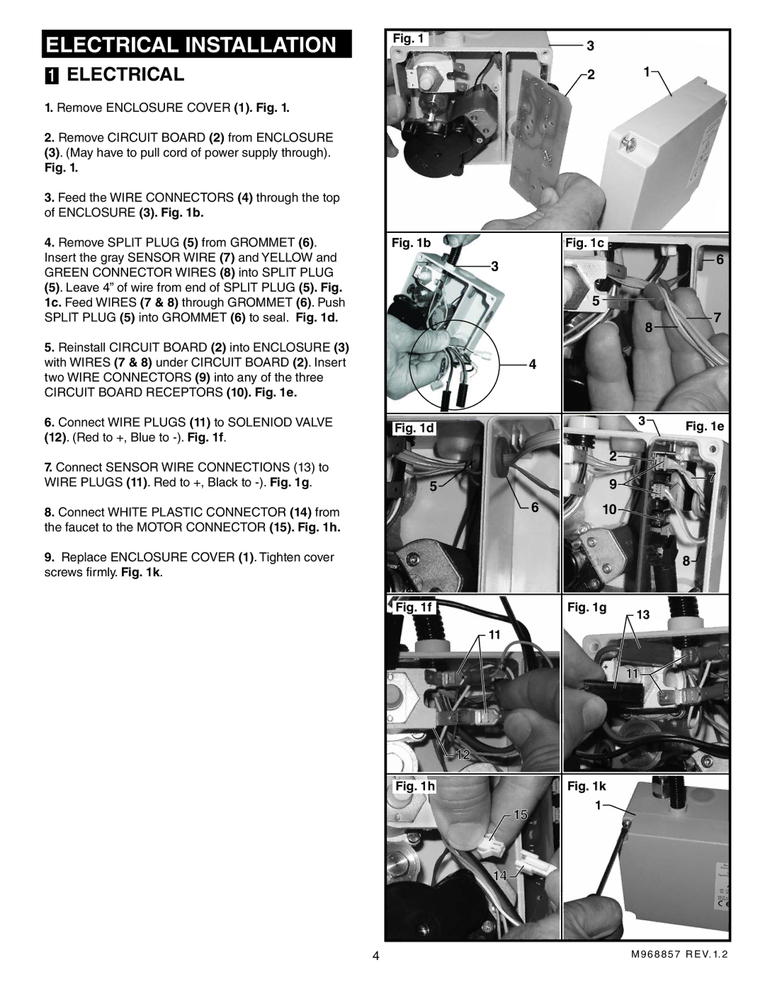
1.Remove ENCLOSURE COVER (1). Fig. 1.
2.Remove CIRCUIT BOARD (2) from ENCLOSURE
(3). (May have to pull cord of power supply through).
Fig. 1.
3.Feed the WIRE CONNECTORS (4) through the top of ENCLOSURE (3). Fig. 1b.
4.Remove SPLIT PLUG (5) from GROMMET (6). Insert the gray SENSOR WIRE (7) and YELLOW and GREEN CONNECTOR WIRES (8) into SPLIT PLUG
(5). Leave 4” of wire from end of SPLIT PLUG (5). Fig. 1c. Feed WIRES (7 & 8) through GROMMET (6). Push SPLIT PLUG (5) into GROMMET (6) to seal. Fig. 1d.
5.Reinstall CIRCUIT BOARD (2) into ENCLOSURE (3) with WIRES (7 & 8) under CIRCUIT BOARD (2). Insert two WIRE CONNECTORS (9) into any of the three CIRCUIT BOARD RECEPTORS (10). Fig. 1e.
6.Connect WIRE PLUGS (11) to SOLENIOD VALVE (12). (Red to +, Blue to
7.Connect SENSOR WIRE CONNECTIONS (13) to WIRE PLUGS (11). Red to +, Black to
8.Connect WHITE PLASTIC CONNECTOR (14) from the faucet to the MOTOR CONNECTOR (15). Fig. 1h.
9.Replace ENCLOSURE COVER (1). Tighten cover screws firmly. Fig. 1k.
Fig. 1 | 3 |
|
|
|
|
| |
| 2 | 1 |
|
Fig. 1b | Fig. 1c |
|
|
3 |
|
| 6 |
|
|
| |
| 5 |
| 7 |
|
| 8 | |
|
|
| |
4 |
|
|
|
Fig. 1d |
| 3 | Fig. 1e |
|
| ||
| 2 |
|
|
5 | 9 |
| 7 |
|
| ||
6 | 10 |
|
|
|
|
| 8 |
Fig. 1f | Fig. 1g | 13 |
|
|
|
| |
11 |
|
|
|
|
| 11 |
|
12 |
|
|
|
Fig. 1h | Fig. 1k |
|
|
15 | 1 |
|
|
|
|
| |
14 |
|
|
|
4 |
| M968857 REV. 1. 2 | |
