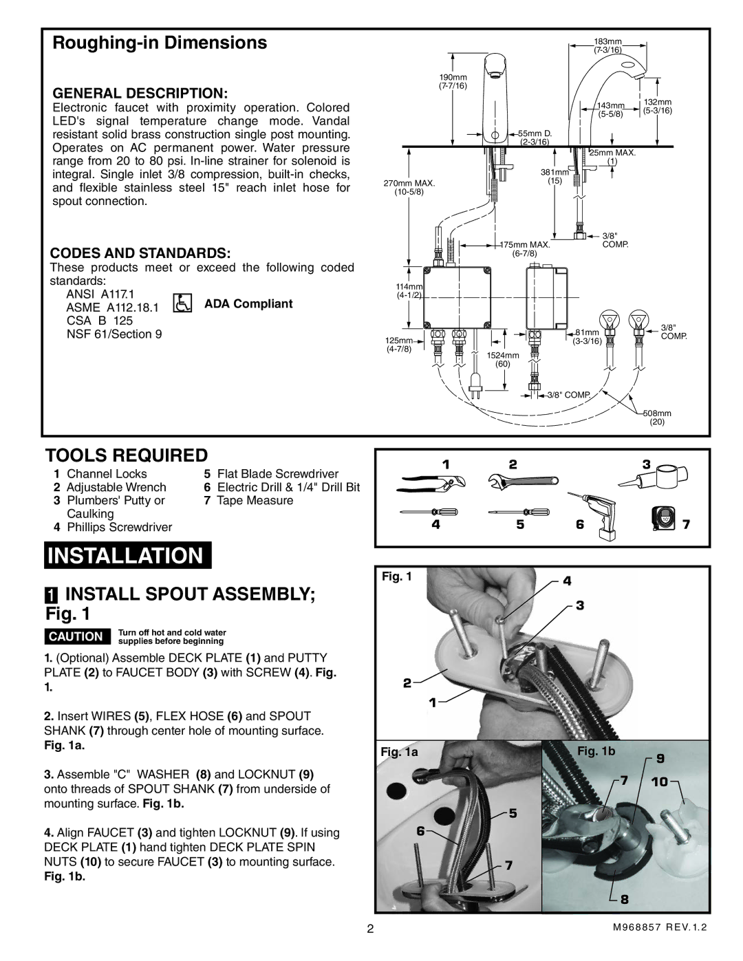
Roughing-in Dimensions
GENERAL DESCRIPTION:
Electronic faucet with proximity operation. Colored LED's signal temperature change mode. Vandal resistant solid brass construction single post mounting. Operates on AC permanent power. Water pressure range from 20 to 80 psi.
CODES AND STANDARDS:
These products meet or exceed the following coded standards:
ANSI A117.1 ASME A112.18.1 CSA B 125
183mm ![]() (7-3/16)
(7-3/16)![]()
190mm
143mm | 132mm | |||
|
|
| ||
| ||||
| 55mm D. |
| |
| 25mm MAX. |
| (1) |
| 381mm |
270mm MAX. | (15) |
|
| 3/8" |
175mm MAX. | COMP. |
|
114mm
NSF 61/Section 9
125mm![]()
1524mm
(60)
81mm
![]() 3/8" COMP.
3/8" COMP.
3/8"
COMP.
508mm
(20)
TOOLS REQUIRED
1 | Channel Locks | 5 | Flat Blade Screwdriver |
2 | Adjustable Wrench | 6 | Electric Drill & 1/4" Drill Bit |
3 | Plumbers' Putty or | 7 | Tape Measure |
| Caulking |
|
|
4Phillips Screwdriver
INSTALLATION
1INSTALL SPOUT ASSEMBLY; Fig. 1
| Turn off hot and cold water | |
CAUTION | ||
supplies before beginning |
1. (Optional) Assemble DECK PLATE (1) and PUTTY |
PLATE (2) to FAUCET BODY (3) with SCREW (4). Fig. |
1. |
2. Insert WIRES (5), FLEX HOSE (6) and SPOUT |
SHANK (7) through center hole of mounting surface. |
1 | 2 |
| 3 |
|
4 | 5 | 6 | 10' | 7 |
Fig. 1 |
| 4 |
|
|
|
|
|
| |
|
| 3 |
|
|
2![]()
1
Fig. 1a. |
3. Assemble "C" WASHER (8) and LOCKNUT (9) |
onto threads of SPOUT SHANK (7) from underside of |
mounting surface. Fig. 1b. |
4. Align FAUCET (3) and tighten LOCKNUT (9). If using |
DECK PLATE (1) hand tighten DECK PLATE SPIN |
NUTS (10) to secure FAUCET (3) to mounting surface. |
Fig. 1b. |
Fig. 1a
![]() 5
5
6![]()
7
Fig. 1b | 9 |
| |
7 | 10 |
![]() 8
8
2 | M968857 REV. 1. 2 |