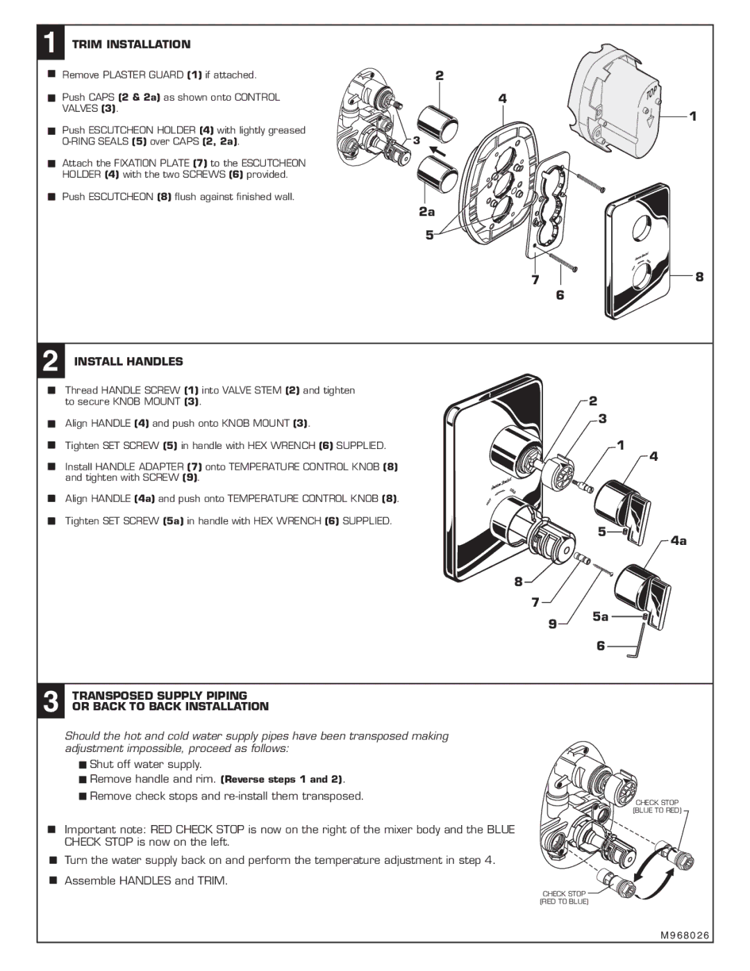
1 TRIM INSTALLATION
Remove PLASTER GUARD (1) if attached.
Push CAPS (2 & 2a) as shown onto CONTROL VALVES (3).
2
4
Push ESCUTCHEON HOLDER (4) with lightly greased
Attach the FIXATION PLATE (7) to the ESCUTCHEON HOLDER (4) with the two SCREWS (6) provided.
Push ESCUTCHEON (8) flush against finished wall.
3![]()
2a
5
1
7 | 8 |
6
12 INSTALL HANDLES
Thread HANDLE SCREW (1) into VALVE STEM (2) and tighten to secure KNOB MOUNT (3).
Align HANDLE (4) and push onto KNOB MOUNT (3).
Tighten SET SCREW (5) in handle with HEX WRENCH (6) SUPPLIED.
Install HANDLE ADAPTER (7) onto TEMPERATURE CONTROL KNOB (8) and tighten with SCREW (9).
Align HANDLE (4a) and push onto TEMPERATURE CONTROL KNOB (8).
Tighten SET SCREW (5a) in handle with HEX WRENCH (6) SUPPLIED.
2
3
1
![]() 4
4
| 5 | 4a |
|
| |
8 |
|
|
7 | 5a |
|
9 |
| |
|
| |
| 6 |
|
3 TRANSPOSED SUPPLY PIPING OR BACK TO BACK INSTALLATION
Should the hot and cold water supply pipes have been transposed making adjustment impossible, proceed as follows:
![]()
![]() Shut off water supply.
Shut off water supply.
![]()
![]() Remove handle and rim. (Reverse steps 1 and 2).
Remove handle and rim. (Reverse steps 1 and 2).
![]() Remove check stops and
Remove check stops and
Important note: RED CHECK STOP is now on the right of the mixer body and the BLUE CHECK STOP is now on the left.
Turn the water supply back on and perform the temperature adjustment in step 4.
Assemble HANDLES and TRIM.
CHECK STOP
(BLUE TO RED)
CHECK STOP
(RED TO BLUE)
M 9 6 8 0 2 6