Piezoelectric Igniter System
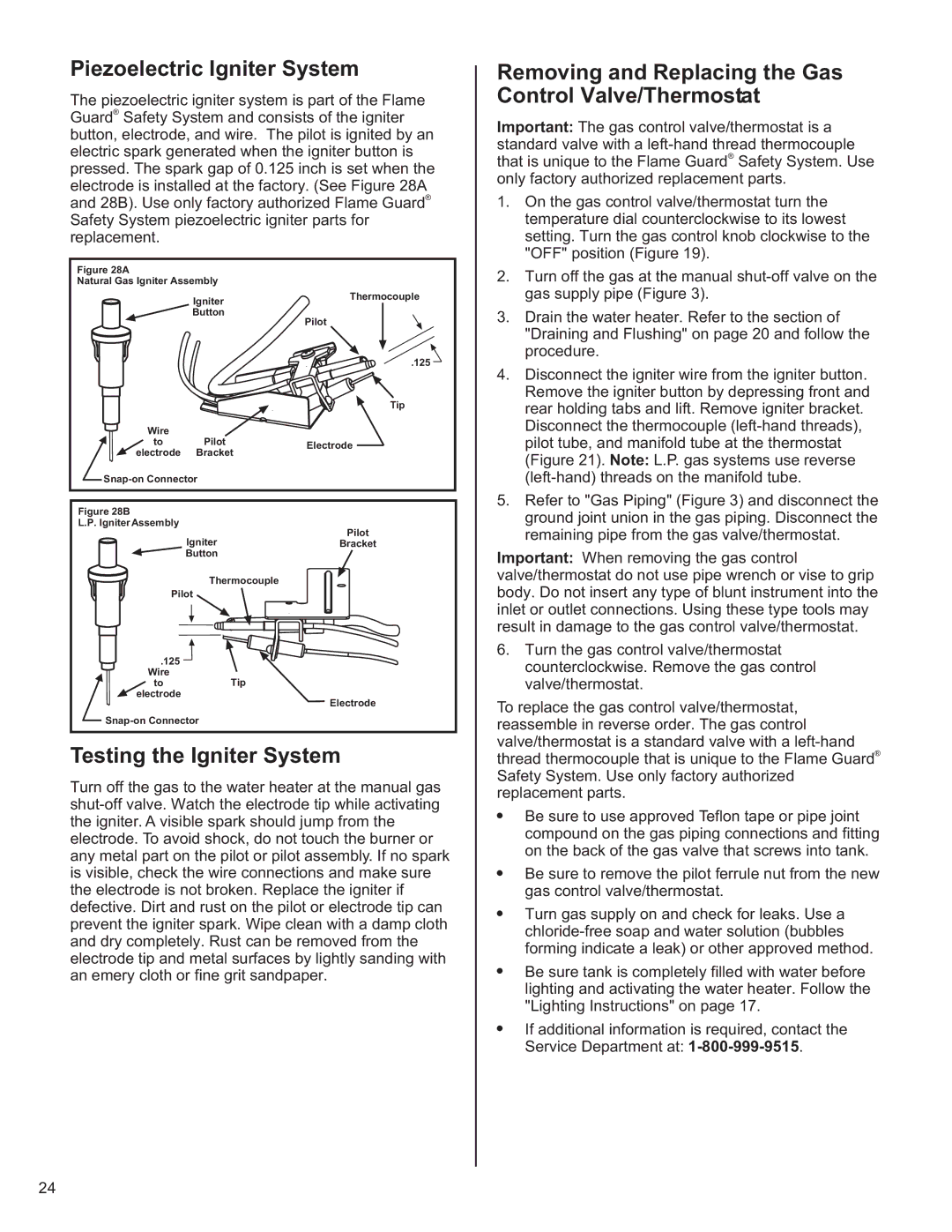
The piezoelectric igniter system is part of the Flame Guard® Safety System and consists of the igniter button, electrode, and wire. The pilot is ignited by an electric spark generated when the igniter button is pressed. The spark gap of 0.125 inch is set when the electrode is installed at the factory. (See Figure 28A and 28B). Use only factory authorized Flame Guard® Safety System piezoelectric igniter parts for replacement.
Removing and Replacing the Gas Control Valve/Thermostat
Important: The gas control valve/thermostat is a standard valve with a
1. On the gas control valve/thermostat turn the |
temperature dial counterclockwise to its lowest |
setting. Turn the gas control knob clockwise to the |
"OFF" position (Figure 19). |
Figure 28A
Natural Gas Igniter Assembly
Igniter
![]() Button
Button
Thermocouple
2. | Turn off the gas at the manual |
| gas supply pipe (Figure 3). |
3. | Drain the water heater. Refer to the section of |
Pilot
.125
Tip
Wire
to PilotElectrode electrode Bracket
![]()
Figure 28B
L.P. Igniter Assembly
Pilot
IgniterBracket
Button
Thermocouple
Pilot
.125 Wire
toTip electrode
Electrode
![]()
Testing the Igniter System
Turn off the gas to the water heater at the manual gas
"Draining and Flushing" on page 20 and follow the |
procedure. |
4. Disconnect the igniter wire from the igniter button. |
Remove the igniter button by depressing front and |
rear holding tabs and lift. Remove igniter bracket. |
Disconnect the thermocouple |
pilot tube, and manifold tube at the thermostat |
(Figure 21). Note: L.P. gas systems use reverse |
5. Refer to "Gas Piping" (Figure 3) and disconnect the |
ground joint union in the gas piping. Disconnect the |
remaining pipe from the gas valve/thermostat. |
Important: When removing the gas control valve/thermostat do not use pipe wrench or vise to grip body. Do not insert any type of blunt instrument into the inlet or outlet connections. Using these type tools may result in damage to the gas control valve/thermostat.
6.Turn the gas control valve/thermostat counterclockwise. Remove the gas control valve/thermostat.
To replace the gas control valve/thermostat, reassemble in reverse order. The gas control valve/thermostat is a standard valve with a
!Be sure to use approved Teflon tape or pipe joint compound on the gas piping connections and fitting on the back of the gas valve that screws into tank.
!Be sure to remove the pilot ferrule nut from the new gas control valve/thermostat.
!Turn gas supply on and check for leaks. Use a
!Be sure tank is completely filled with water before lighting and activating the water heater. Follow the "Lighting Instructions" on page 17.
!If additional information is required, contact the Service Department at:
24