Installation Requirements
Gas Supply System
Low pressure building gas supply systems are defined as those systems that cannot under any circumstances exceed 14” W.C. (1/2 PSI Gauge). These systems do not require pressure regulation. Measurements should be taken to insure that gas pressures are stable and fall within the requirements stated on the water heater rating plate. Readings should be taken with all gas burning equipment off (static pressure) and with all gas burning equipment running at maximum rate (dynamic pressure). The gas supply pressure must be stable within 1.5” W.C. from static to dynamic pressure to provide good performance. Pressure drops that exceed 1.5” W.C. may cause rough starting, noisy combustion or nuisance outages. Increases or spikes in static pressure during off cycles may cause failure to ignite or in severe cases damage to appliance gas valves. If your low pressure system does NOT meet these requirements, the installer is responsible for the corrections.
High Pressure building supply systems use pressures that exceed 14” W.C. (1/2 PSI Gauge). These systems must use field supplied regulators to lower the gas pressure to less than 14” W.C. (1/2 PSI Gauge). Appliances require gas regulators that are properly sized for the water heater input and deliver the rating plate specified pressures. Gas supply systems where pressure exceeds 5 PSI often require multiple regulators to achieve desired pressures. Systems in excess of 5 PSI building pressure should be designed by gas delivery professionals for best performance. Water heaters connected to gas supply systems that exceed 14” W.C. (1/2 PSI Gauge) at any time must be equipped with a gas supply regulator.
Gas Pressure Requirements
All models require a minimum gas supply pressure of 5.2” W.C. The minimum supply pressure is measured while gas is flowing (dynamic pressure). The supply pressure (dynamic) should never fall below 5.2” W.C. The supply pressure should be measured with all gas fired appliances connected to the common main firing at full capacity. If the supply pressure drops more than 1.5” W.C. as gas begins to flow to the water heater then the supply gas system including the gas line and/or the gas regulator may be restricted or undersized. See Supply Gas Regulator section and Gas Piping section of this manual. The low gas pressure switch will shut down the water heater if the supply gas pressure drops below the minimum allowable value.
The gas valve on all models has a maximum gas supply pressure limit of 14" W.C. The maximum supply pressure is measured while gas is not flowing (static pressure).
Supply Gas Regulator
The maximum allowable gas supply pressure for this water heater is 14.0 inches W.C. (3.48 kPa). Install a positive
If a positive
1.Positive
2.Positive
3.After installing the positive
addition adjustment maybe required later to maintain a steady gas supply pressure.
4.When installing multiple water heaters in the same gas supply system it is recommended that individual positive
Power Supply
The water heaters covered in this manual require a 120 VAC, 1Ø (single phase), 60Hz, 15 amp power supply and must also be electrically grounded in accordance with local codes or, in the absence of local codes, with the National Electrical Code, ANSI/ NFPA 70 or the Canadian Electrical Code, CSA C22.1.
Water Temperature Control and Mixing Valves
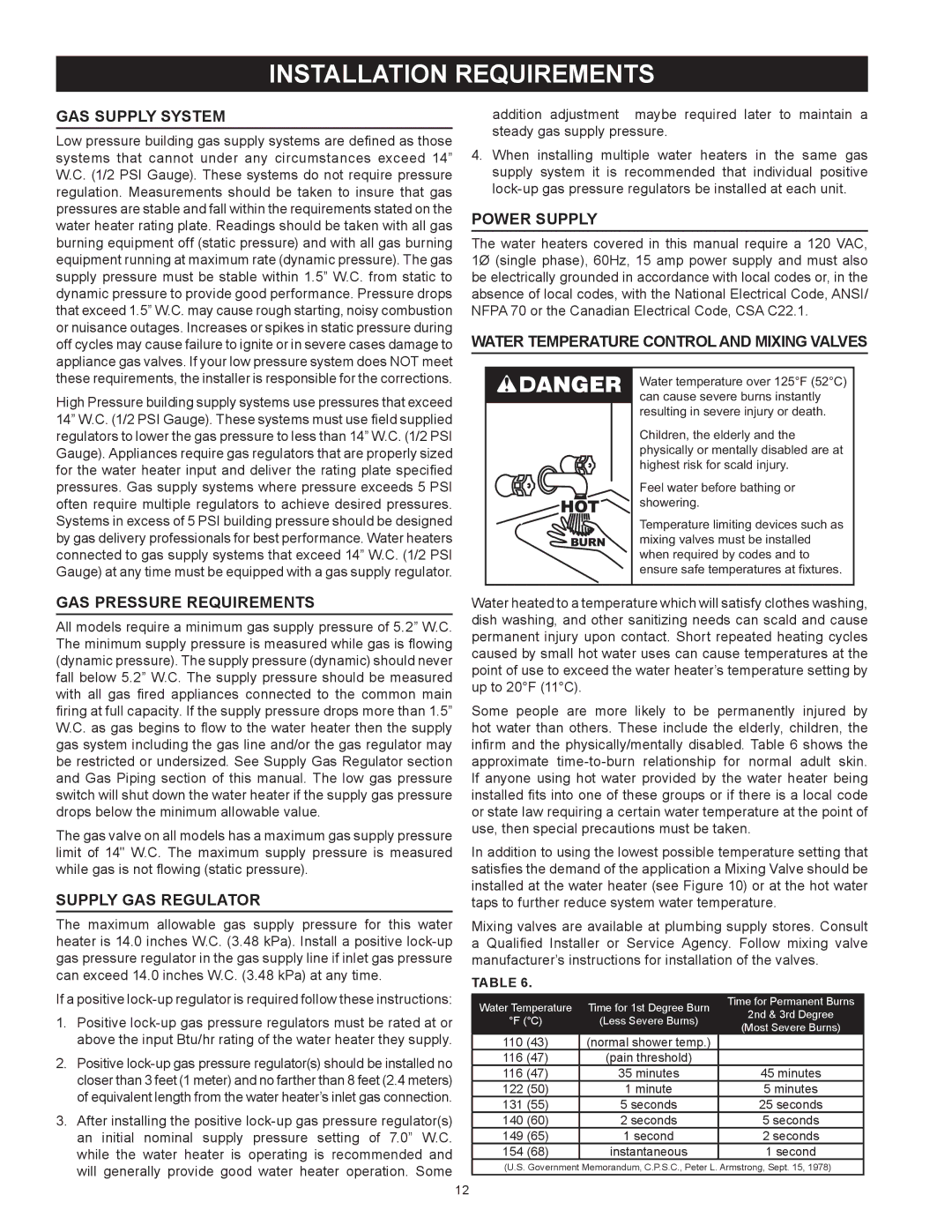
Water temperature over 125°F (52°C) can cause severe burns instantly resulting in severe injury or death.
Children, the elderly and the physically or mentally disabled are at highest risk for scald injury.
Feel water before bathing or showering.
Temperature limiting devices such as mixing valves must be installed when required by codes and to ensure safe temperatures at fixtures.
Water heated to a temperature which will satisfy clothes washing, dish washing, and other sanitizing needs can scald and cause permanent injury upon contact. Short repeated heating cycles caused by small hot water uses can cause temperatures at the point of use to exceed the water heater’s temperature setting by up to 20°F (11°C).
Some people are more likely to be permanently injured by hot water than others. These include the elderly, children, the infirm and the physically/mentally disabled. Table 6 shows the approximate
In addition to using the lowest possible temperature setting that satisfies the demand of the application a Mixing Valve should be installed at the water heater (see Figure 10) or at the hot water taps to further reduce system water temperature.
Mixing valves are available at plumbing supply stores. Consult a Qualified Installer or Service Agency. Follow mixing valve manufacturer’s instructions for installation of the valves.
Table 6.
Water Temperature | Time for 1st Degree Burn | Time for Permanent Burns | |
2nd & 3rd Degree | |||
°F (°C) | (Less Severe Burns) | ||
(Most Severe Burns) | |||
|
| ||
110 (43) | (normal shower temp.) |
| |
116 (47) | (pain threshold) |
| |
116 (47) | 35 minutes | 45 minutes | |
122 (50) | 1 minute | 5 minutes | |
131 (55) | 5 seconds | 25 seconds | |
140 (60) | 2 seconds | 5 seconds | |
149 (65) | 1 second | 2 seconds | |
154 (68) | instantaneous | 1 second |
(U.S. Government Memorandum, C.P.S.C., Peter L. Armstrong, Sept. 15, 1978)
12