Maintenance
Check the Igniter Assembly and Main Burners
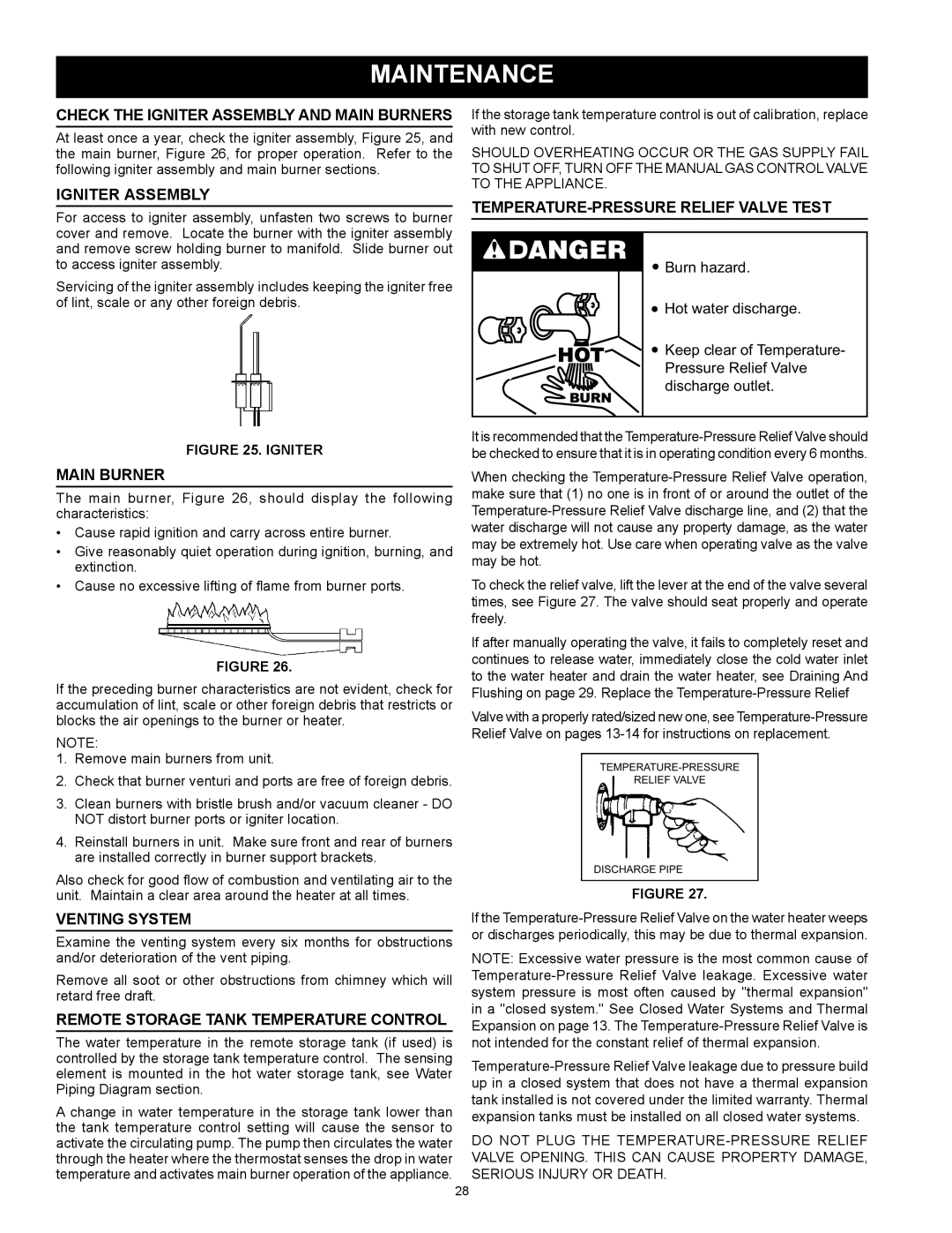
At least once a year, check the igniter assembly, Figure 25, and the main burner, Figure 26, for proper operation. Refer to the following igniter assembly and main burner sections.
Igniter Assembly
For access to igniter assembly, unfasten two screws to burner cover and remove. Locate the burner with the igniter assembly and remove screw holding burner to manifold. Slide burner out to access igniter assembly.
Servicing of the igniter assembly includes keeping the igniter free of lint, scale or any other foreign debris.
Figure 25. IGNITER
Main Burner
The main burner, Figure 26, should display the following characteristics:
•Cause rapid ignition and carry across entire burner.
•Give reasonably quiet operation during ignition, burning, and extinction.
•Cause no excessive lifting of flame from burner ports.
Figure 26.
If the preceding burner characteristics are not evident, check for accumulation of lint, scale or other foreign debris that restricts or blocks the air openings to the burner or heater.
NOTE:
1.Remove main burners from unit.
2.Check that burner venturi and ports are free of foreign debris.
3.Clean burners with bristle brush and/or vacuum cleaner - DO NOT distort burner ports or igniter location.
4.Reinstall burners in unit. Make sure front and rear of burners are installed correctly in burner support brackets.
Also check for good flow of combustion and ventilating air to the unit. Maintain a clear area around the heater at all times.
Venting System
Examine the venting system every six months for obstructions and/or deterioration of the vent piping.
Remove all soot or other obstructions from chimney which will retard free draft.
Remote Storage Tank Temperature Control
The water temperature in the remote storage tank (if used) is controlled by the storage tank temperature control. The sensing element is mounted in the hot water storage tank, see Water Piping Diagram section.
A change in water temperature in the storage tank lower than the tank temperature control setting will cause the sensor to activate the circulating pump. The pump then circulates the water through the heater where the thermostat senses the drop in water temperature and activates main burner operation of the appliance.
If the storage tank temperature control is out of calibration, replace with new control.
SHOULD OVERHEATING OCCUR OR THE GAS SUPPLY FAIL TO SHUT OFF, TURN OFF THE MANUAL GAS CONTROL VALVE TO THE APPLIANCE.
Temperature-Pressure Relief Valve Test
![]() Burn hazard.
Burn hazard.
![]() Hot water discharge.
Hot water discharge.
![]() Keep clear of Temperature- Pressure Relief Valve discharge outlet.
Keep clear of Temperature- Pressure Relief Valve discharge outlet.
It is recommended that the
When checking the
To check the relief valve, lift the lever at the end of the valve several times, see Figure 27. The valve should seat properly and operate freely.
If after manually operating the valve, it fails to completely reset and continues to release water, immediately close the cold water inlet to the water heater and drain the water heater, see Draining And Flushing on page 29. Replace the
Valve with a properly rated/sized new one, see
FIGURE 27.
If the
NOTE: Excessive water pressure is the most common cause of
DO NOT PLUG THE
28
