FEATURES AND COMPONENTS
The Eliminator (self-cleaning system)
These units include The Eliminator
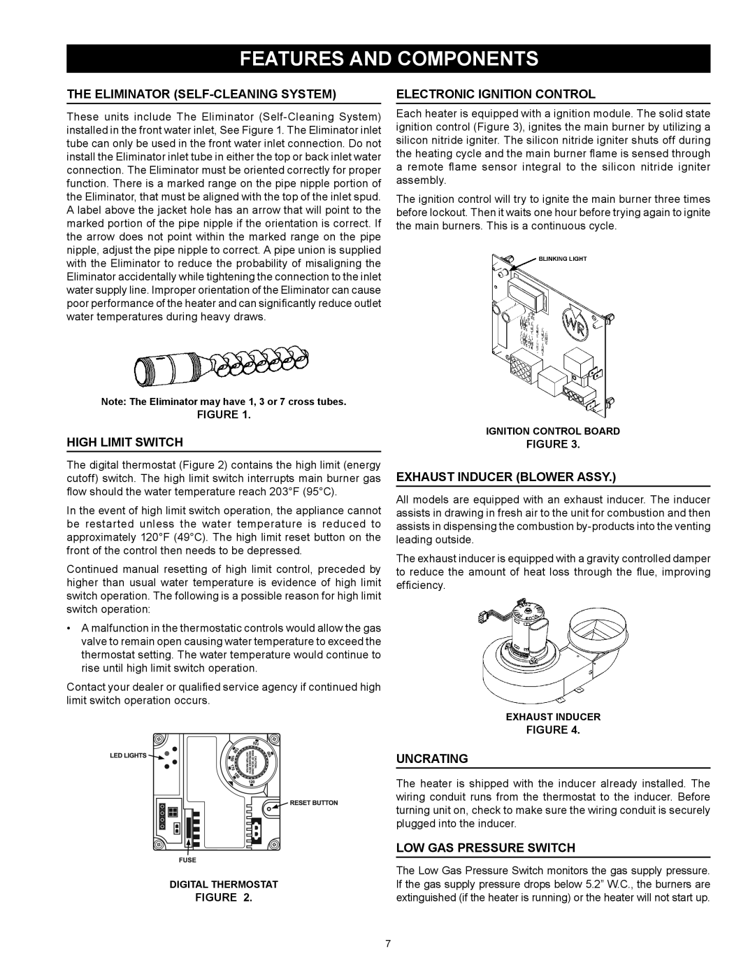
Note: The Eliminator may have 1, 3 or 7 cross tubes.
FIGURE 1.
High Limit Switch
The digital thermostat (Figure 2) contains the high limit (energy cutoff) switch. The high limit switch interrupts main burner gas flow should the water temperature reach 203°F (95°C).
In the event of high limit switch operation, the appliance cannot be restarted unless the water temperature is reduced to approximately 120°F (49°C). The high limit reset button on the front of the control then needs to be depressed.
Continued manual resetting of high limit control, preceded by higher than usual water temperature is evidence of high limit switch operation. The following is a possible reason for high limit switch operation:
•A malfunction in the thermostatic controls would allow the gas valve to remain open causing water temperature to exceed the thermostat setting. The water temperature would continue to rise until high limit switch operation.
Contact your dealer or qualified service agency if continued high limit switch operation occurs.
DIGITAL THERMOSTAT
FIGURE 2.
Electronic Ignition Control
Each heater is equipped with a ignition module. The solid state ignition control (Figure 3), ignites the main burner by utilizing a silicon nitride igniter. The silicon nitride igniter shuts off during the heating cycle and the main burner flame is sensed through a remote flame sensor integral to the silicon nitride igniter assembly.
The ignition control will try to ignite the main burner three times before lockout. Then it waits one hour before trying again to ignite the main burners. This is a continuous cycle.
IGNITION CONTROL BOARD
FIGURE 3.
Exhaust Inducer (blower assy.)
All models are equipped with an exhaust inducer. The inducer assists in drawing in fresh air to the unit for combustion and then assists in dispensing the combustion
The exhaust inducer is equipped with a gravity controlled damper to reduce the amount of heat loss through the flue, improving efficiency.
EXHAUST INDUCER
FIGURE 4.
Uncrating
The heater is shipped with the inducer already installed. The wiring conduit runs from the thermostat to the inducer. Before turning unit on, check to make sure the wiring conduit is securely plugged into the inducer.
Low Gas Pressure Switch
The Low Gas Pressure Switch monitors the gas supply pressure. If the gas supply pressure drops below 5.2” W.C., the burners are extinguished (if the heater is running) or the heater will not start up.
7