On multiple water heater installations the supply gas line regulators shall be adjusted to provide gas pressure to each water heater within the minimum and maximum supply pressure requirements listed in Table 3 on page 8 with all gas fired appliances connected to a common gas main firing at full capacity.
Note: A pressure drop of more than 1.5” W. C. (0.37 kPa) when the Main Burner ignites is an indication of an inadequate supply of gas and can lead to ignition failure, rough starts and/ or rough operation. If a drop of more than 1.5” W. C. (0.37 kPa) in supply gas pressure occurs when the Main Burner ignites, ensure the supply gas lines and regulator(s) are properly sized and installed. See the requirements for Supply Gas Regulator on page 12 and Gas Piping on page 23. Ensure all requirements and installation instructions are maintained.
Checking Venting
The following steps shall be followed with each appliance connected to the venting system placed in operation, while any other appliances connected to the venting system are not in operation.
1.Seal any unused openings in the venting system.
2.Inspect the venting system for proper size and horizontal pitch, as required in the National Fuel Gas Code, ANSI Z223.1or the CAN/CGA B149 Installation Codes and these instructions. Determine that there is no blockage or restriction, leakage, corrosion and other deficiencies which could cause an unsafe condition.
3.So far as is practical, close all building doors and windows and all doors between the space in which the water heater(s) connected to the venting system are located and other spaces of the building. Turn on all appliances not connected to the venting system. Turn on all exhaust fans, such as range hoods and bathroom exhausts, so they shall operate at maximum speed. Close fireplace dampers.
4.Follow the lighting instruction. Place the water heater being inspected in operation. Adjust thermostat so appliance shall operate continuously.
5.Test for spillage at the burner level after 5 minutes of main burner operation.
6.After it has been determined that each appliance connected to the venting system properly vents when tested as outlined above, return doors, windows, exhaust fans, fireplace dampers and any other gas burning appliance to their previous conditions of use.
7.If improper venting is observed during any of the above tests, the venting system must be corrected.
FAILURE TO CORRECT BACK DRAFTS MAY CAUSE AIR CONTAMINATION AND UNSAFE CONDITIONS.
•If the back draft cannot be corrected by the normal method or if a suitable draft cannot be obtained, a blower type flue gas exhauster must be employed to assure proper venting and correct combustion.
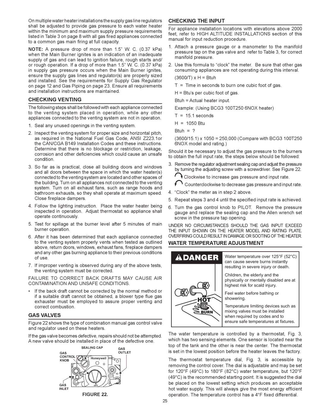
Gas Valves
Figure 22 shows the type of combination manual gas control valve and regulator used on these heaters.
If the gas valve becomes defective, repairs should not be attempted. A new valve should be installed in place of the defective one.
Figure 22.
Checking the Input
For appliance installation locations with elevations above 2000 feet, refer to HIGH ALTITUDE INSTALLATIONS section of this manual for input reduction procedure.
1.Attach a pressure gauge or a manometer to the manifold pressure tap on the gas valve and refer to Table 3, for correct manifold pressure.
2.Use this formula to “clock” the meter. Be sure that other gas consuming appliances are not operating during this interval. (3600/T) x H = Btuh
T = Time in seconds to burn one cubic foot of gas. H = Btu’s per cubic foot of gas.
Btuh = Actual heater input.
Example: (Using BCG3 100T250 6NOX heater) T = 15.1 seconds
H = 1050 Btu Btuh = ?
(3600/15.1) x 1050 = 250,000 (Compare with BCG3 100T250 6NOX model and rating.)
Should it be necessary to adjust the gas pressure to the burners to obtain the full input rate, the steps below should be followed:
3.Remove the regulator adjustment sealing cap and adjust the pressure by turning the adjusting screw with a screwdriver. See Figure 22.
![]() Clockwise to increase gas pressure and input rate.
Clockwise to increase gas pressure and input rate. ![]() Counterclockwise to decrease gas pressure and input rate.
Counterclockwise to decrease gas pressure and input rate.
4.“Clock” the meter as in step 2 above.
5.Repeat steps 3 and 4 until the specified input rate is achieved.
6.Turn the gas control knob to PILOT. Remove the pressure gauge and replace the sealing cap and the Allen wrench set screw in the pressure tap opening.
UNDER NO CIRCUMSTANCES SHOULD THE GAS INPUT EXCEED THE INPUT SHOWN ON THE HEATER MODEL AND RATING PLATE. OVERFIRING COULD RESULT IN DAMAGE OR SOOTING OF THE HEATER.
Water Temperature Adjustment
Water temperature over 125°F (52°C) can cause severe burns instantly resulting in severe injury or death.
Children, the elderly and the physically or mentally disabled are at highest risk for scald injury.
Feel water before bathing or showering.
Temperature limiting devices such as mixing valves must be installed when required by codes and to ensure safe temperatures at fixtures.
The water temperature is controlled by a thermostat, Fig. 3, which has two sensing elements. One sensor is located near the top of the tank and the other is near the center. The thermostat is set in the lowest position before the heater leaves the factory.
The thermostat temperature dial, Fig. 3, is accessible by removing the control cover. The dial is adjustable and may be set for 120°F (49°C) to 180°F (82°C) water temperature, but 120°F (49°C) is the recommended starting point. It is suggested the dial be placed on the lowest setting which produces an acceptable hot water supply. This will always give the most energy efficient operation. The temperature control has a 4°F fixed differential.
25