Configuration and Installation
Configuration and Installation
Setting the Internal Jumpers
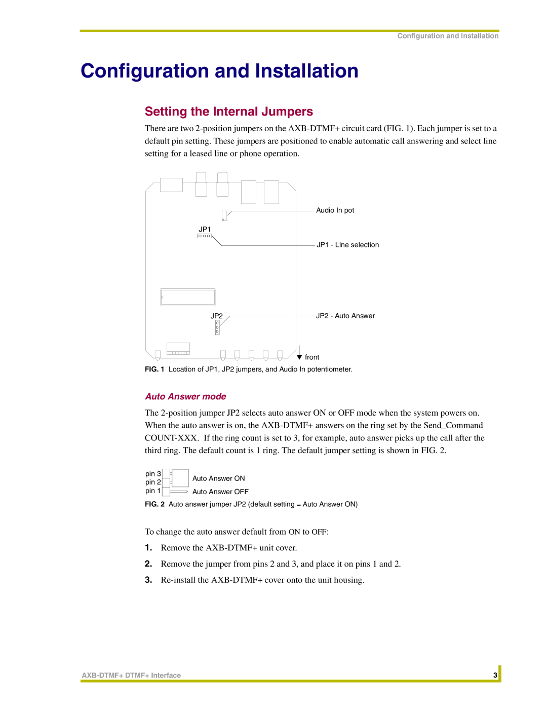
There are two 2-position jumpers on the AXB-DTMF+ circuit card (FIG. 1). Each jumper is set to a default pin setting. These jumpers are positioned to enable automatic call answering and select line setting for a leased line or phone operation.
Audio In pot
JP1
JP1 - Line selection
JP2JP2 - Auto Answer
 front
front
FIG. 1 Location of JP1, JP2 jumpers, and Audio In potentiometer.
Auto Answer mode
The 2-position jumper JP2 selects auto answer ON or OFF mode when the system powers on. When the auto answer is on, the AXB-DTMF+ answers on the ring set by the Send_Command COUNT-XXX. If the ring count is set to 3, for example, auto answer picks up the call after the third ring. The default count is 1 ring. The default jumper setting is shown in FIG. 2.
pin 3 | | | | Auto Answer ON |
pin 2 | | | |
| | | |
pin 1 | | | | Auto Answer OFF |
FIG. 2 Auto answer jumper JP2 (default setting = Auto Answer ON)
To change the auto answer default from ON to OFF:
1.Remove the AXB-DTMF+ unit cover.
2.Remove the jumper from pins 2 and 3, and place it on pins 1 and 2.
3.Re-install the AXB-DTMF+ cover onto the unit housing.
AXB-DTMF+ DTMF+ Interface | 3 | |
| | |