Wiring and Installation
Wiring the IR Sensors and Receivers
The IR Sensors and Receivers use a
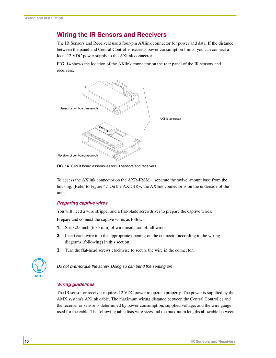
FIG. 14 shows the location of the AXlink connector on the rear panel of the IR sensors and receivers.
Sensor circuit board assembly
AXlink connector
Receiver circuit board assembly
FIG. 14 Circuit board assemblies for IR sensors and receivers
To access the AXlink connector on the
Preparing captive wires
You will need a wire stripper and a
Prepare and connect the captive wires as follows.
1.Strip .25 inch (6.35 mm) of wire insulation off all wires.
2.Insert each wire into the appropriate opening on the connector according to the wiring diagrams (following) in this section.
3.Turn the
Do not
Wiring guidelines
The IR sensor or receiver requires 12 VDC power to operate properly. The power is supplied by the AMX system's AXlink cable. The maximum wiring distance between the Central Controller and the receiver or sensor is determined by power consumption, supplied voltage, and the wire gauge used for the cable. The following table lists wire sizes and the maximum lengths allowable between
| 10 | IR Sensors and Receivers |
|
|
|