Installation Sheet
RDM-FDB Single Channel Lutron FDB Ballast Dimmer 1920 W
The
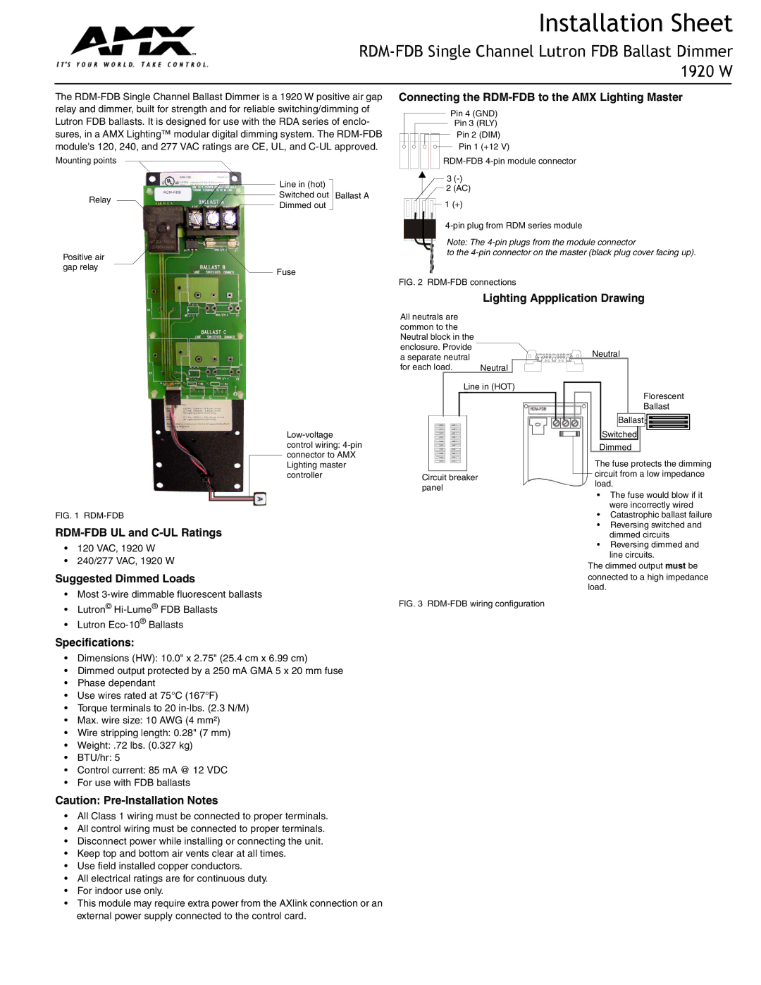
Mounting points
Line in (hot)
Relay ![]()
![]() Switched out Ballast A Dimmed out
Switched out Ballast A Dimmed out
Positive air
gap relay
Fuse
Connecting the RDM-FDB to the AMX Lighting Master
Pin 4 (GND)
Pin 3 (RLY)
Pin 2 (DIM)
Pin 1 (+12 V)
3
![]() 2 (AC)
2 (AC) ![]() 1 (+)
1 (+)
Note: The
to the
FIG. 2 RDM-FDB connections
Lighting Appplication Drawing
FIG. 1 RDM-FDB
•120 VAC, 1920 W
•240/277 VAC, 1920 W
Suggested Dimmed Loads
•Most
•Lutron©
•Lutron
Specifications:
•Dimensions (HW): 10.0" x 2.75" (25.4 cm x 6.99 cm)
•Dimmed output protected by a 250 mA GMA 5 x 20 mm fuse
•Phase dependant
•Use wires rated at 75°C (167°F)
•Torque terminals to 20
•Max. wire size: 10 AWG (4 mm²)
•Wire stripping length: 0.28" (7 mm)
•Weight: .72 lbs. (0.327 kg)
•BTU/hr: 5
•Control current: 85 mA @ 12 VDC
•For use with FDB ballasts
Caution:
All neutrals are |
|
common to the |
|
Neutral block in the |
|
enclosure. Provide |
|
a separate neutral |
|
for each load. | Neutral |
Line in (HOT)
Circuit breaker panel
FIG. 3 RDM-FDB wiring configuration
Neutral
Florescent
Ballast
BallastBALLAST ![]()
![]()
![]()
![]()
Switched
Dimmed
The fuse protects the dimming circuit from a low impedance load.
•The fuse would blow if it were incorrectly wired
•Catastrophic ballast failure
•Reversing switched and dimmed circuits
•Reversing dimmed and line circuits.
The dimmed output must be connected to a high impedance load.
•All Class 1 wiring must be connected to proper terminals.
•All control wiring must be connected to proper terminals.
•Disconnect power while installing or connecting the unit.
•Keep top and bottom air vents clear at all times.
•Use field installed copper conductors.
•All electrical ratings are for continuous duty.
•For indoor use only.
•This module may require extra power from the AXlink connection or an external power supply connected to the control card.