4. Operation Instructions
The H300 could take as long as ten minutes for the display to completely “ settle” and display the actual temperature or relative humidity level if the meter is exposed to two vastly different environments. The sensors used to make the environmental measurements must have time to acclimate to the test environment.
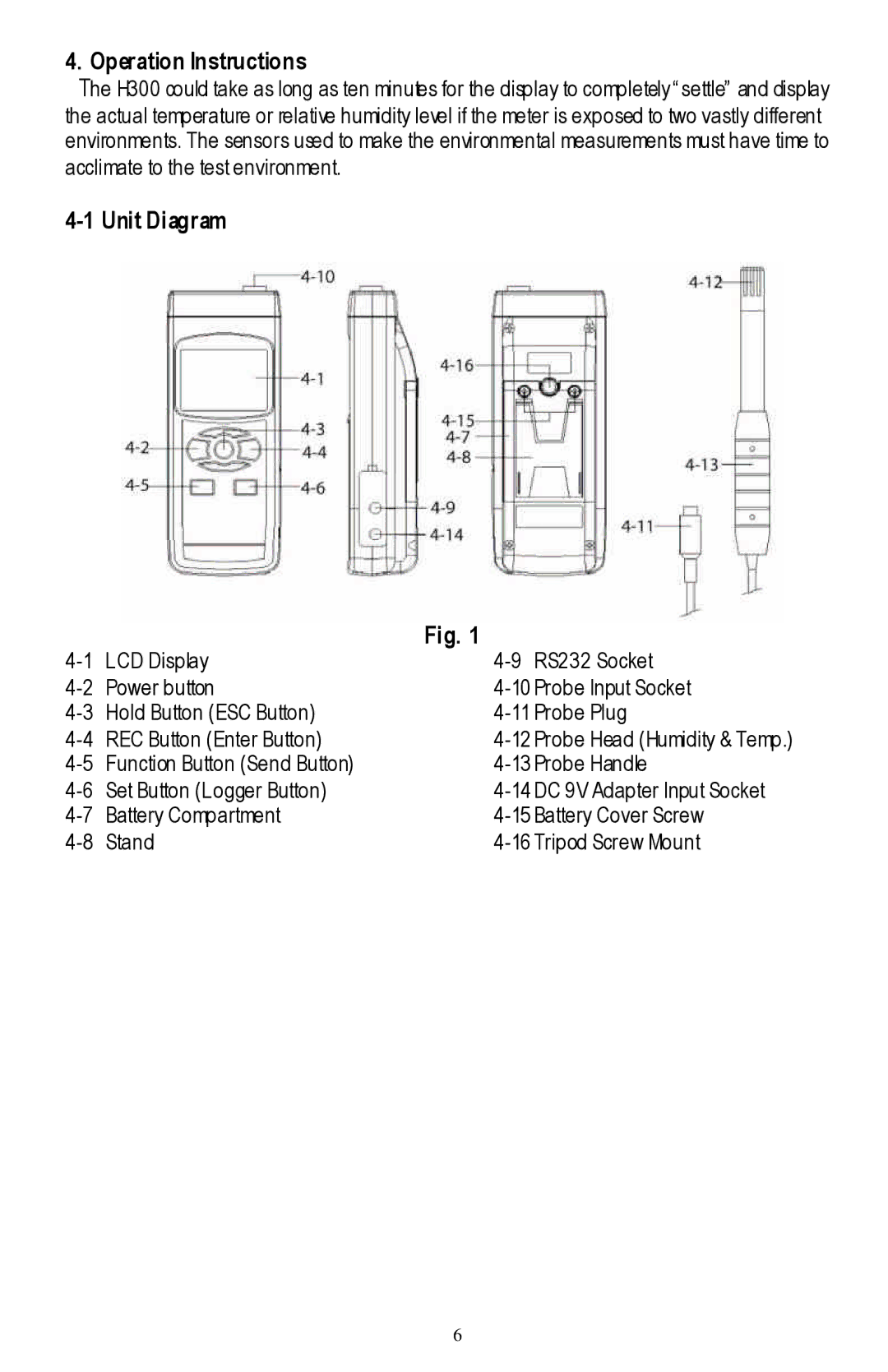
4-1 Unit Diagram
Fig. 1
LCD Display | 4 | ||
Power button | 4 | ||
Hold Button (ESC Button) | 4 | ||
REC Button (Enter Button) | 4 | ||
4 | |||
Set Button (Logger Button) | 4 | ||
Battery Compartment | 4 | ||
Stand | 4 | ||
6