SPECIFICATIONS
ABSOLUTE MAXIMUM RATINGS
INPUT VOLTAGE | +24 TO +75 VDC |
|
|
OUTPUT CURRENT | 6 AMPS PEAK |
|
|
PLATE TEMPERATURE | 70° C |
|
|
STORAGE TEMPERATURE | 40° TO +125° C |
|
|
INPUT CURRENT (PINS 1, 2, 4, 5) | 15 mA Max |
|
|
ELECTRICAL SPECIFICATIONS (TA=25EC, V+ = 75VDC)
ITEM | TEST CONDITION | MIN TYP | MAX | UNIT |
|
|
|
| S |
|
|
|
|
|
Input Voltage |
| 24 | 75 | V |
|
|
|
|
|
Phase Output Current | RMS | 1 | 4 | A |
Phase Output Current | Peak | 1.4 | 6 | A |
DETERMINING OUTPUT CURRENT
The output current for the motor used when microstepping is determined differently from that of a halfstep/fullstep unipolar driver. In the MDM60001, a sine/cosine output current is used in rotating the motor. The output current for a given motor is determined by the motors current rating and the configuration for how the motor is hooked up. There is a current adjustment resistor used to set the output current of the MDM60001. This sets the peak output current of the sine/cosine waves. The specified motor current (which is the RMS value) is multiplied by a factor of 0.7, 1.0, or 1.4 depending on the motor configuration
SETTING OUTPUT CURRENT
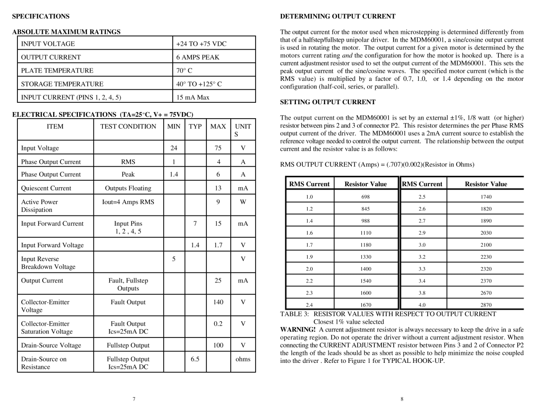
The output current on the MDM60001 is set by an external ±1%, 1/8 watt (or higher ) resistor between pins 2 and 3 of connector P2. This resistor determines the per Phase RMS output current of the driver. The MDM60001 uses a 2mA current source to establish the reference voltage needed to control the output current. The relationship between the output current and the resistor value is as follows:
RMS OUTPUT CURRENT (Amps) = (.707)(0.002)(Resistor in Ohms)
Quiescent Current | Outputs Floating |
| 13 | mA |
Active Power | Iout=4 Amps RMS |
| 9 | W |
Dissipation |
|
|
|
|
|
|
|
|
|
Input Forward Current | Input Pins | 7 | 15 | mA |
| 1, 2 , 4, 5 |
|
|
|
|
|
|
|
|
Input Forward Voltage |
| 1.4 | 1.7 | V |
|
|
|
|
|
Input Reverse |
| 5 |
| V |
Breakdown Voltage |
|
|
|
|
|
|
|
|
|
Output Current | Fault, Fullstep |
| 25 | mA |
| Outputs |
|
|
|
|
|
|
|
|
Fault Output |
| 140 | V | |
Voltage |
|
|
|
|
RMS Current | Resistor Value |
1.0 | 698 |
|
|
1.2 | 845 |
|
|
1.4 | 988 |
|
|
1.6 | 1110 |
|
|
1.7 | 1180 |
|
|
1.9 | 1330 |
|
|
2.0 | 1400 |
|
|
2.2 | 1540 |
|
|
2.3 | 1600 |
|
|
2.4 | 1670 |
RMS Current | Resistor Value |
2.5 | 1740 |
|
|
2.6 | 1820 |
|
|
2.7 | 1890 |
|
|
2.9 | 2030 |
|
|
3.0 | 2100 |
|
|
3.2 | 2230 |
|
|
3.3 | 2320 |
|
|
3.4 | 2370 |
|
|
3.8 | 2670 |
|
|
4.0 | 2870 |
Fault Output | 0.2 | V | |
Saturation Voltage | Ics=25mA DC |
|
|
|
|
|
|
Fullstep Output | 100 | V | |
|
|
|
|
Fullstep Output | 6.5 | ohms | |
Resistance | Ics=25mA DC |
|
|
TABLE 3: RESISTOR VALUES WITH RESPECT TO OUTPUT CURRENT Closest 1% value selected
WARNING! A current adjustment resistor is always necessary to keep the drive in a safe operating region. Do not operate the driver without a current adjustment resistor. When connecting the CURRENT ADJUSTMENT resistor between Pins 3 and 2 of Connector P2 the length of the leads should be as short as possible to help minimize the noise coupled into the driver . Refer to Figure 1 for TYPICAL
7 | 8 |