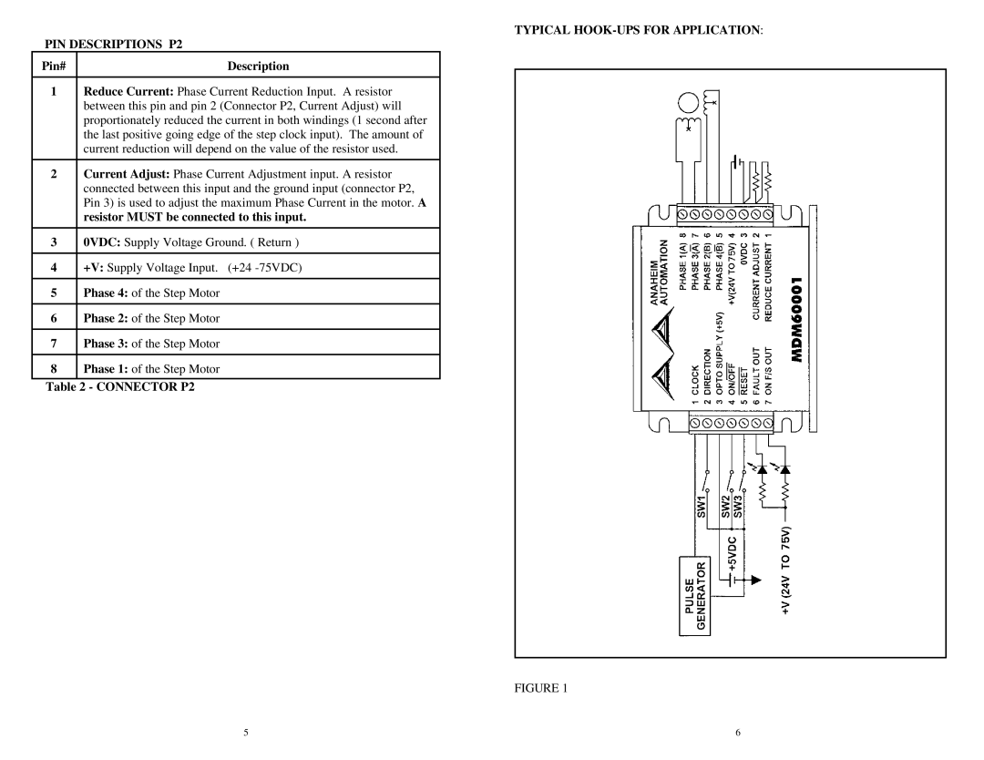
TYPICAL HOOK-UPS FOR APPLICATION:
PIN DESCRIPTIONS P2
Pin# | Description |
|
|
1 | Reduce Current: Phase Current Reduction Input. A resistor |
| between this pin and pin 2 (Connector P2, Current Adjust) will |
| proportionately reduced the current in both windings (1 second after |
| the last positive going edge of the step clock input). The amount of |
| current reduction will depend on the value of the resistor used. |
|
|
2 | Current Adjust: Phase Current Adjustment input. A resistor |
| connected between this input and the ground input (connector P2, |
| Pin 3) is used to adjust the maximum Phase Current in the motor. A |
| resistor MUST be connected to this input. |
|
|
3 | 0VDC: Supply Voltage Ground. ( Return ) |
|
|
4 | +V: Supply Voltage Input. (+24 |
|
|
5 | Phase 4: of the Step Motor |
|
|
6 | Phase 2: of the Step Motor |
|
|
7 | Phase 3: of the Step Motor |
|
|
8 | Phase 1: of the Step Motor |
|
|
Table 2 - CONNECTOR P2
FIGURE 1
5 | 6 |