Jumper Settings
Power Select Jumper (JP1)
By default, the power select jumper, JP1, must have no jumpers on any of its pins. The jumpers can be used only when the extender is plugged into an ADSP-BF537 EZ-KIT Lite (see Table 2-1).
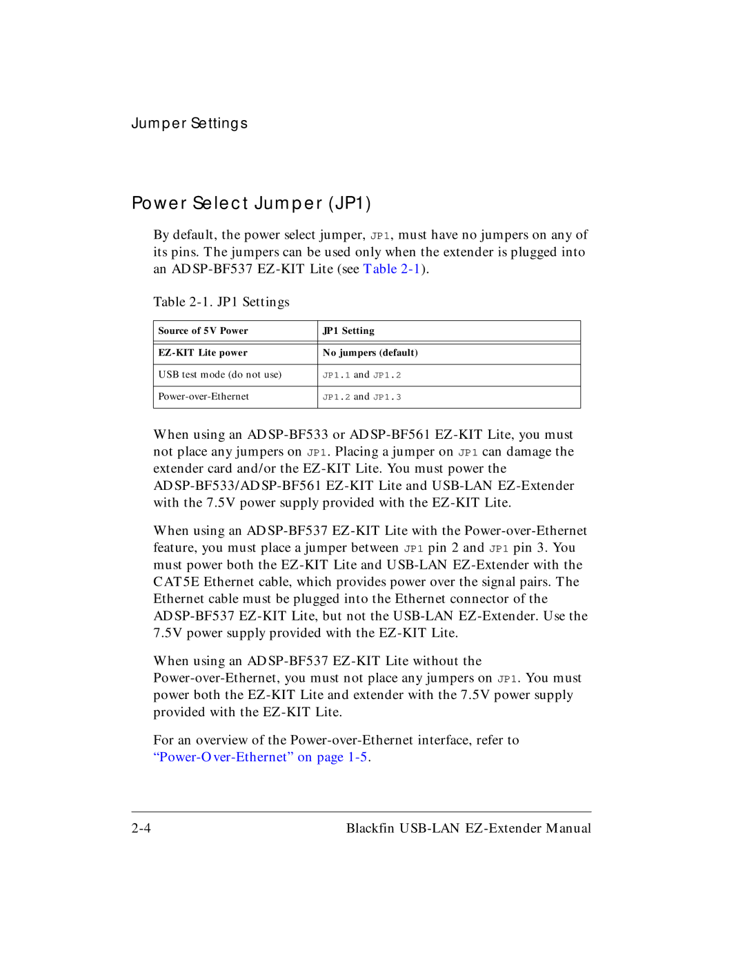
Table 2-1. JP1 Settings
Source of 5V Power | JP1 Setting |
| |
| |
EZ-KIT Lite power | No jumpers (default) |
| |
USB test mode (do not use) | JP1.1 and JP1.2 |
| |
Power-over-Ethernet | JP1.2 and JP1.3 |
| |
When using an ADSP-BF533 or ADSP-BF561 EZ-KIT Lite, you must not place any jumpers on JP1. Placing a jumper on JP1 can damage the extender card and/or the EZ-KIT Lite. You must power the ADSP-BF533/ADSP-BF561 EZ-KIT Lite and USB-LAN EZ-Extender with the 7.5V power supply provided with the EZ-KIT Lite.
When using an ADSP-BF537 EZ-KIT Lite with the Power-over-Ethernet feature, you must place a jumper between JP1 pin 2 and JP1 pin 3. You must power both the EZ-KIT Lite and USB-LAN EZ-Extender with the CAT5E Ethernet cable, which provides power over the signal pairs. The Ethernet cable must be plugged into the Ethernet connector of the ADSP-BF537 EZ-KIT Lite, but not the USB-LAN EZ-Extender. Use the 7.5V power supply provided with the EZ-KIT Lite.
When using an ADSP-BF537 EZ-KIT Lite without the Power-over-Ethernet, you must not place any jumpers on JP1. You must power both the EZ-KIT Lite and extender with the 7.5V power supply provided with the EZ-KIT Lite.
For an overview of the Power-over-Ethernet interface, refer to “Power-Over-Ethernet” on page 1-5.
2-4 | Blackfin USB-LAN EZ-Extender Manual |