Analog Devices 82-000845-01 manual Test Mode Enable Switch SW1.4, Serial ROM Enable Switch SW2.1

Models: 82-000845-01

1 48
Download 48 pages 58.61 Kb
Page 30
Image 30

Switch Settings

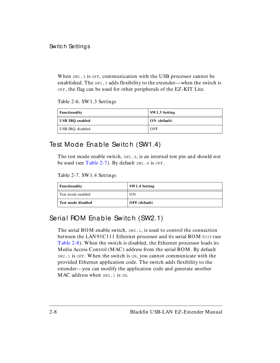
When SW1.3 is OFF, communication with the USB processor cannot be established. The SW1.3 adds flexibility to the extender—when the switch is OFF, the flag can be used for other peripherals of the EZ-KIT Lite.

Table 2-6. SW1.3 Settings

Functionality

SW1.3 Setting


USB IRQ enabled

ON (default)


USB IRQ disabled

OFF


Test Mode Enable Switch (SW1.4)

The test mode enable switch, SW1.4, is an internal test pin and should not be used (see Table 2-7). By default SW1.4 is OFF.

Table 2-7. SW1.4 Settings

Functionality

SW1.4 Setting


Test mode enabled

ON


Test mode disabled

OFF (default)


Serial ROM Enable Switch (SW2.1)

The serial ROM enable switch, SW2.1, is used to control the connection between the LAN91C111 Ethernet processor and its serial ROM (U3) (see Table 2-8). When the switch is disabled, the Ethernet processor loads its Media Access Control (MAC) address from the serial ROM. By default SW2.1 is OFF. When the switch is ON, you cannot communicate with the provided Ethernet application code. The switch adds flexibility to the extender—you can modify the application code and generate another MAC address when SW2.1 is ON.

2-8

Blackfin USB-LAN EZ-Extender Manual

Page 30
Image 30
Analog Devices 82-000845-01 manual Test Mode Enable Switch SW1.4, Serial ROM Enable Switch SW2.1