Ethernet Interface
The USB IRQ line of the extender connects to PF10 on the ADSP-BF533/ADSP-BF561 processors and PF7 on the ADSP-BF537 pro- cessors. The flag pins can be used for push buttons or LEDs on the respective EZ-KIT Lites; consequently, the user must make the proper changes to that EZ-KIT Lite.
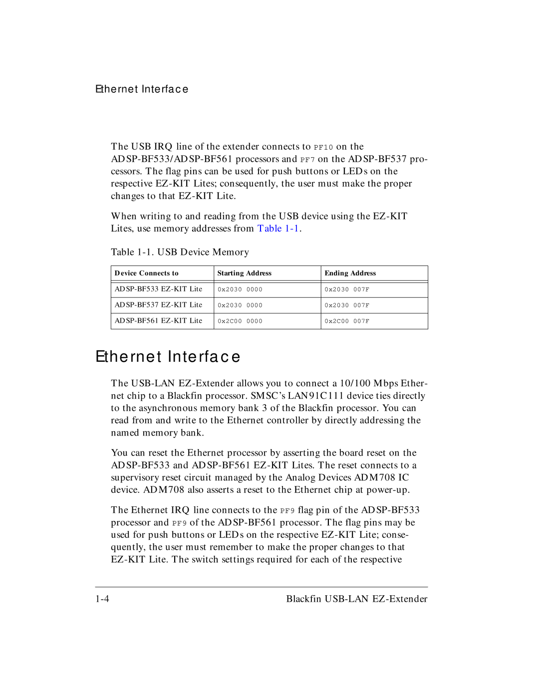
When writing to and reading from the USB device using the EZ-KIT Lites, use memory addresses from Table 1-1.
Table 1-1. USB Device Memory
Device Connects to | Starting Address | Ending Address |
| | | | |
| | | | |
ADSP-BF533 EZ-KIT Lite | 0x2030 | 0000 | 0x2030 | 007F |
| | | | |
ADSP-BF537 EZ-KIT Lite | 0x2030 | 0000 | 0x2030 | 007F |
| | |
ADSP-BF561 EZ-KIT Lite | 0x2C00 0000 | 0x2C00 007F |
| | | | |
Ethernet Interface
The USB-LAN EZ-Extender allows you to connect a 10/100 Mbps Ether- net chip to a Blackfin processor. SMSC’s LAN91C111 device ties directly to the asynchronous memory bank 3 of the Blackfin processor. You can read from and write to the Ethernet controller by directly addressing the named memory bank.
You can reset the Ethernet processor by asserting the board reset on the ADSP-BF533 and ADSP-BF561 EZ-KIT Lites. The reset connects to a supervisory reset circuit managed by the Analog Devices ADM708 IC device. ADM708 also asserts a reset to the Ethernet chip at power-up.
The Ethernet IRQ line connects to the PF9 flag pin of the ADSP-BF533 processor and PF9 of the ADSP-BF561 processor. The flag pins may be used for push buttons or LEDs on the respective EZ-KIT Lite; conse- quently, the user must remember to make the proper changes to that EZ-KIT Lite. The switch settings required for each of the respective
1-4 | Blackfin USB-LAN EZ-Extender |
