Manuals
/
Andrew
/
Home Audio
/
Stereo System
Andrew
7.6-Meter ESA
manual
Installation Procedures
Models:
7.6-Meter ESA
1
31
69
69
Download
69 pages
15.91 Kb
28
29
30
31
32
33
34
35
Install
Lubrication Chart
Maintenance
Support Legs Assembly Step
Subreflector Adjustment
Customer Service Center
Page 31
Image 31
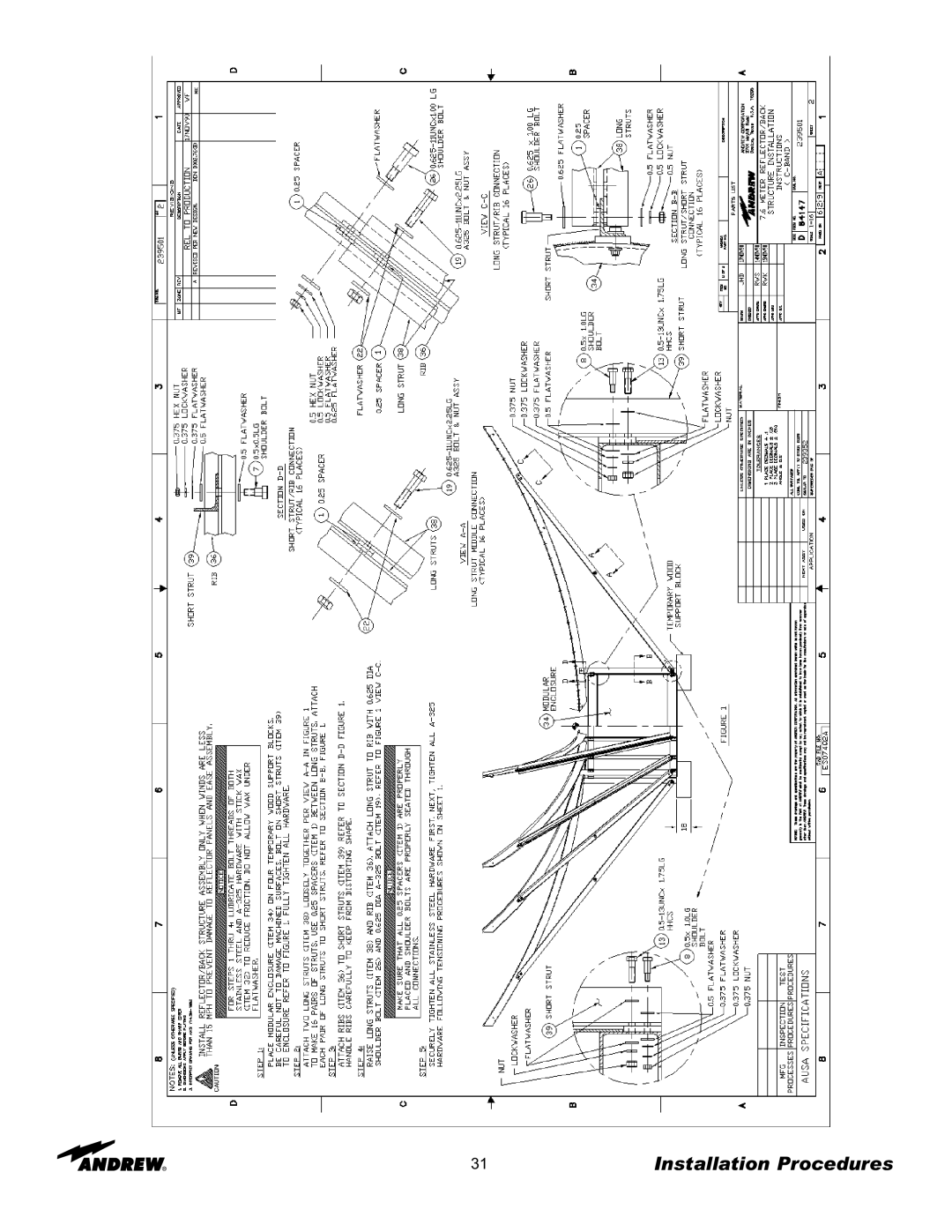
31
Installation Procedures
Page 30
Page 32
Page 31
Image 31
Page 30
Page 32
Contents
Meter ESA
Table of Contents
Introduction
Meter Earth Station Antenna
Proprietary Data Information and Assistance Technical
Customer Service Center
How to Use This Manual
Overview Content
Getting Started
Overview
Tool Size Quantity
Recommended Tools
Getting Started
Returning Equipment Step
Overview Foundation Preparation
Installation Procedures
1b A-325 Tensioning For bolts over four diameters
Tensioning Step
Tripod Ground Mount Assembly Azimuth Beam Assembly Step
Support Legs Assembly Step
Step
Step
Panning Frame Assembly Step
Step
Step
Step
Step
Step
Step
Elevation Jackscrew Assembly Step
Step
Azimuth Jackscrew Assembly Step Mount Assembly
Joint Assembly
Pivot Assembly
Step
221923/223180 221738 200088A
Installation Procedures
Installation Procedures
Installation Procedures
Installation Procedures
Installation Procedures
Installation Procedures
Installation Procedures
Installation Procedures
Installation Procedures
Installation Procedures
Installation Procedures
Installation Procedures
Installation Procedures
Installation Procedures
Installation Procedures
Installation Procedures
Installation Procedures
Installation Procedures
Installation Procedures
Installation Procedures
Installation Procedures
Installation Procedures
Installation Procedures
Installation Procedures
Operation
Overview Acquiring a Satellite
Step
Polarization at 45 degrees from Optimum Setting
Maximizing Odd Transponders
Subreflector Adjustment
Preventive Maintenance
Overview General Cleaning Electrical Parts
Preventive Maintenance
Antenna
Preventive Maintenance
Drive System Voltage Current Checks Step
Step
Preventive Maintenance
Jackscrews/Motors Gear Motor/Housing Fill Drain Requirements
Lubrication Chart
High-Speed Antenna Lubrication Points
Medium-Speed Antenna Lubrication Points
Top
Page
Image
Contents