| TM |
Model 410C | Section II |
| Paragraphs |
SECTION II
INSTALLATION
| |||||
| mechanically and electrically, before shipment. It | ||||
| should be physically free of mars or scratches and in | ||||
| perfect electrical order upon receipt. To confirm | ||||
| this, the instrument should be inspected for physical | ||||
| damage in transit. Also, check for supplied acces- | ||||
. | sories, and test | the electrical performance of the in- | |||
strument using | the procedure outlined in Paragraph | ||||
| |||||
| damage or deficiency, refer to | ||||
| paragraph |
| |||
| INSTALLATION. |
| |||
| Model 410C is transistorized except for | ||||
| one vacuum tube and requires no special cooling. | ||||
| However, the instrument should not be operated where | ||||
| the ambient temperature exceeds 55° C (140° F). | ||||
|
| ||||
| |||||
| for bench use. However, when used in combination | ||||
| with other submodular units, it can be bench and/or | ||||
| rack mounted. | The Combining Cases and Adapter | |||
| Frame are designed specifically for this purpose. | ||||
| |||||
| The Combining Cases are | ||||
| accept various | combinations of submodular units. | |||
| Beinga full width unit, it can either be bench or rack | ||||
| mounted. An illustration of the Combining Case is | ||||
| shown in Figure | ||||
| Model 410C are shown in Figure |
| |||
|
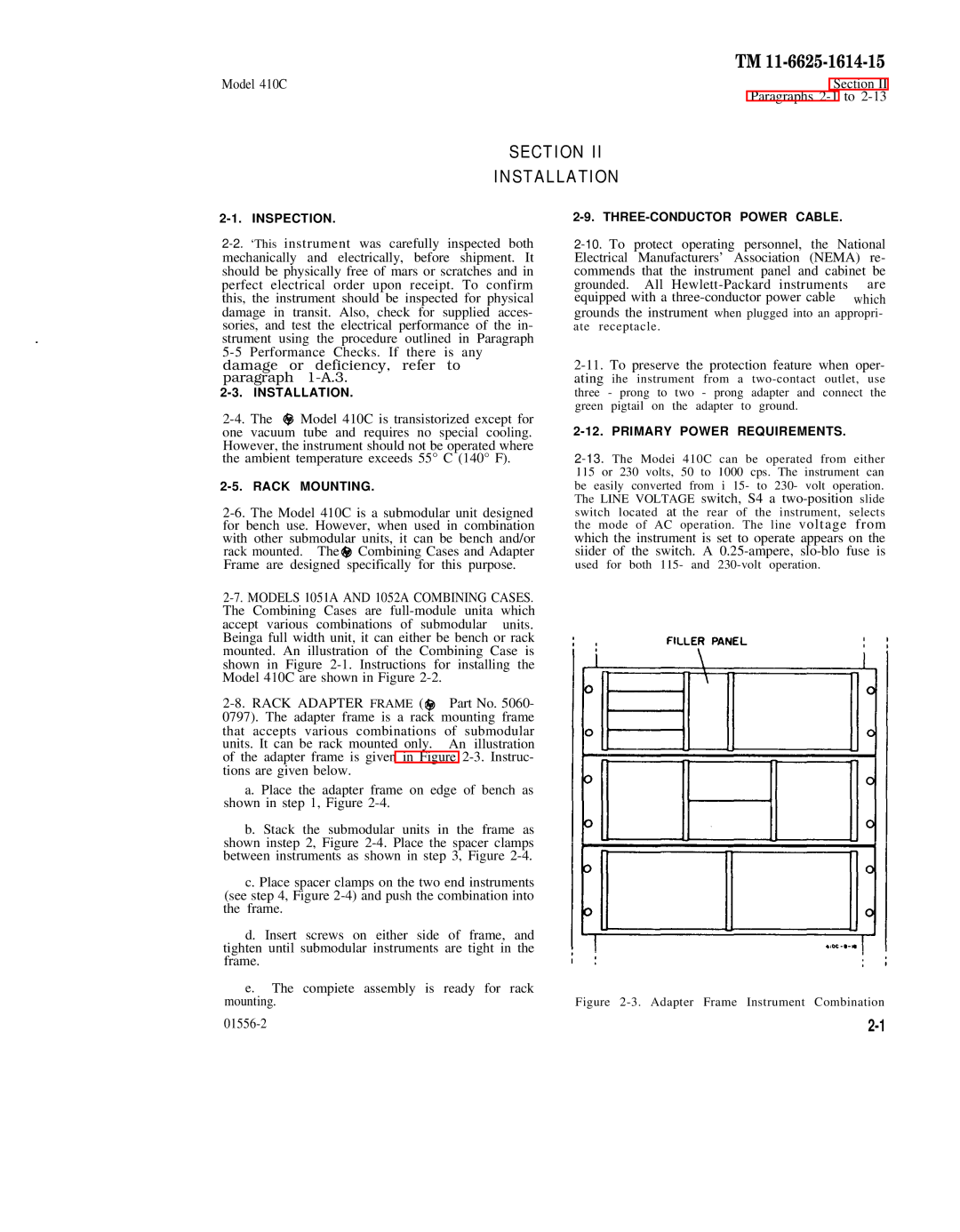
| Part No. 5060- | |||
| 0797). The adapter frame is a rack mounting frame | ||||
| that accepts various combinations of submodular | ||||
| units. It can be rack mounted only. | An illustration | |||
| of the adapter frame is given in Figure | ||||
| tions are given below. |
| |||
|
| a. Place the adapter frame on edge of bench as | |||
| shown in step 1, Figure |
| |||
|
| b. Stack the submodular units in the frame as | |||
| shown instep 2, Figure | ||||
| between instruments as shown in step 3, Figure | ||||
|
| c. Place spacer clamps on the two end instruments | |||
| (see step 4, Figure | ||||
| the | frame. |
|
|
|
d. Insert screws on either side of frame, and tighten until submodular instruments are tight in the frame.
e.The compiete assembly is ready for rack mounting.
grounded. All | are |
equipped with a | which |
grounds the instrument when plugged into an appropri- ate receptacle.
three green
2-12. PRIMARY POWER REQUIREMENTS.
switch located at the rear of the instrument, selects the mode of AC operation. The line voltage from which the instrument is set to operate appears on the siider of the switch. A
used for both 115- and