TM
b . U s e a c v o l t m e t e r t o v e r i f y M o d e l 4 1 0 C l i n e
voltage of 115 v . Chopper frequency will vary with line voltage variations .
c . C o n n e c t 4 1 0 C , e l e c t r o n i c c o u n t e r , a n d
voltmeter | as ahown in | Figure 5 - 6 . 1 . |
|
| |
d . Set | M o d e l 4 1 0 C | F U N C T I O N | S E L E C T O R | t o | |
+ D C V ; R A N G E t o 1 . 5 V . |
|
|
| ||
e . Adjust voltmeter | calibrator | to supply + 5 V | dc | ||
to the Model 410C (DCV and | COM | cables) . |
| ||
f. | Observe | counter, | and | adjust A3R5 for a chop- |
per | frequency | of 100 | cps ( | ±2 cps) . |
5 - 2 9 . P o w e r S u p p l y A d j u s t m e n t
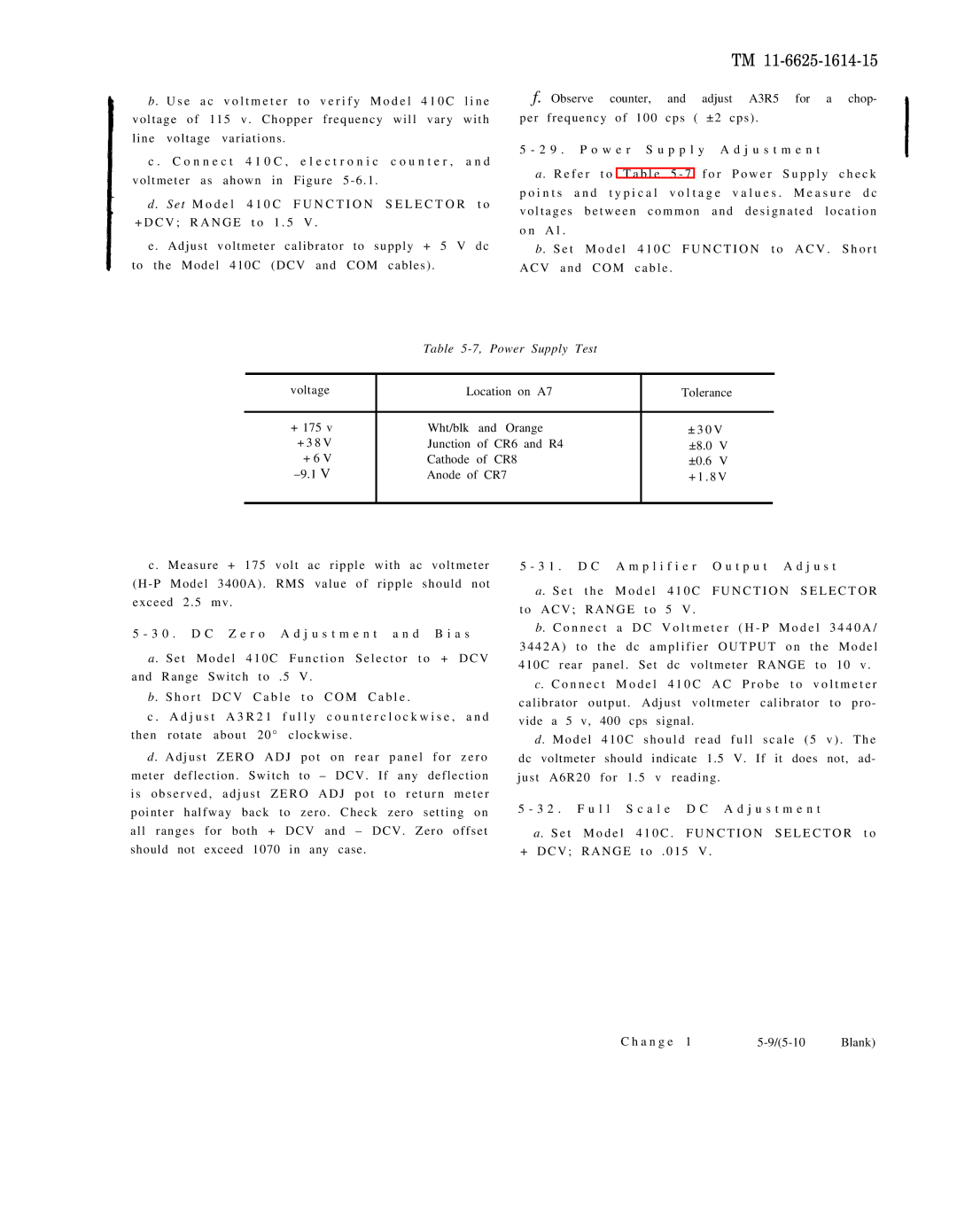
a . R e f e r t o T a b l e 5 - 7 f o r P o w e r S u p p l y c h e c k p o i n t s a n d t y p i c a l v o l t a g e v a l u e s . M e a s u r e d c v o l t a g e s b e t w e e n c o m m o n a n d d e s i g n a t e d l o c a t i o n o n A l .
b . S e t M o d e l 4 1 0 C F U N C T I O N t o A C V . S h o r t A C V a n d C O M c a b l e .
Table 5-7, Power Supply Test
voltage | Location on A7 | Tolerance |
| |
|
|
|
| |
+ 175 v | Wht/blk and Orange | ± 3 0 V |
| |
+ 3 8 V | Junction of CR6 and R4 | ±8.0 | V |
|
+ 6 V | Cathode of CR8 | ±0.6 | V |
|
Anode of CR7 | + 1 . 8 V |
| ||
|
|
|
|
|
c . Measure + 175 volt ac ripple with ac voltmeter (H - P Model 3400A) . RMS value of ripple should not exceed 2 . 5 mv .
5 - 3 0 . D C Z e r o A d j u s t m e n t a n d B i a s
a . S e t M o d e l 4 1 0 C F u n c t i o n S e l e c t o r t o + D C V and Range Switch to . 5 V .
b . S h o r t D C V C a b l e t o C O M C a b l e .
c . A d j u s t A 3 R 2 1 f u l l y c o u n t e r c l o c k w i s e , a n d then rotate about 20° clockwise .
d . A d j u s t Z E R O A D J p o t o n r e a r p a n e l f o r z e r o meter deflection . Switch to – DCV . If any deflection i s o b s e r v e d , a d j u s t Z E R O A D J p o t t o r e t u r n m e t e r pointer halfway back to zero . Check zero setting on all ranges for both + DCV and – DCV . Zero offset should not exceed 1070 in any case.
5 - 3 1 . D C A m p l i f i e r O u t p u t A d j u s t
a. S e t t h e M o d e l 4 1 0 C F U N C T I O N S E L E C T O R
t o A C V ; R A N G E t o 5 V .
b. C o n n e c t a D C V o l t m e t e r ( H - P M o d e l 3 4 4 0 A / 3 4 4 2 A ) t o t h e d c a m p l i f i e r O U T P U T o n t h e M o d e l
410C rear panel . Set dc voltmeter RANGE to 10 v .
c. C o n n e c t M o d e l 4 1 0 C A C P r o b e t o v o l t m e t e r
calibrator output . Adjust voltmeter calibrator to pro - vide a 5 v, 400 cps signal.
d . M o d e l 4 1 0 C s h o u l d r e a d f u l l s c a l e ( 5 v ) . T h e
dc voltmeter should indicate 1.5 V. If it does not, ad- just A6R20 for 1 . 5 v reading .
5 - 3 2 . F u l l S c a l e D C A d j u s t m e n t
a. S e t M o d e l 4 1 0 C . F U N C T I O N S E L E C T O R t o + D C V ; R A N G E t o . 0 1 5 V .
C h a n g e 1 | Blank) |