TM
Model 410C | Section V |
Paragraphs |
SECTION V
MAINTENANCE
5 - 1 . I N T R O D U C T I O N . |
| 5 - 9 . M e c h a n i c a l M E T E R Z E R O . | |||||
This section contains | maintenance procedures |
|
|
|
| ||
a. Turn instrument on. | Allow at least a 20 | ||||||
for | the Model 410C Electronic Voltmeter. | ||||||
minute |
|
| |||||
TEST EQUIPMENT | REQUIRED. |
|
| ||||
|
|
|
| ||||
5 - 5 . PERFORMANCE CHECKS .
5 - 6 . The performance checks presented in this section are front panel operations designed to com- pare the Model 410C with it’s published specifications. These operations may be incorporated in periodic maintenance, post repair and incoming quality control checks. These operations should be conducted before any attempt is made at instrument calibration or adjustment. During performance checks, periodically vary the line voltage to the Model 410C, ± 10% on either 115v or 230 v operation. A 1/2 hour
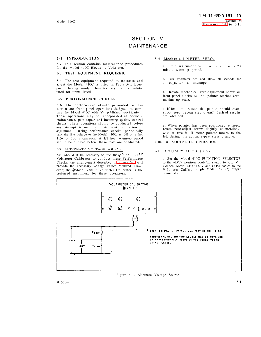
5-7. ALTERNATE VOLTAGE SOURCE.
![]()
Voltmeter Calibrator to conduct these Performance Checks, the arrangement described in Figure ![]() Model 738BR Voltmeter Calibrator is the preferred instrument for these operations.
Model 738BR Voltmeter Calibrator is the preferred instrument for these operations.
b. Turn voltmeter off, and allow 30 seconds for all capacitors to discharge.
c.Rotate mechanical
d.If for some reason the pointer should over- shoot zero, repeat step c until desired results are obtained.
e. When pointer has been positioned at zero, rotate
5-10. DC VOLTMETER OPERATION.
5-11. ACCURACY CHECK (DCV).
a. Set the Model 410C FUNCTION SELECTOR to the +DCV position; RANGE switch to. 015 V .
Connect Model 410C DCV and COM cables to the
Voltmeter Calibrator ![]() Model 738BR) output terminals .
Model 738BR) output terminals .