Model 410C
second maY be made without loss of accuracy by re- moving the. plastic nose on the Model 11036A and using in its place a 0.25 microfarad blocking capacitor in series with the exposed contact of the probe.
THE GRAY INSULATING MATERIAL
AROUND THE AC PROBE IS POLY-
STYRENE, A
MATERIAL. IT IS NOT POSSIBLE TO
SOLDER TO THE CONTACT WHICH IS
EXPOSED WITH THE PROBE NOSE IS
REMOVED WITHOUT DESTROYING
THE POLYSTYRENE.
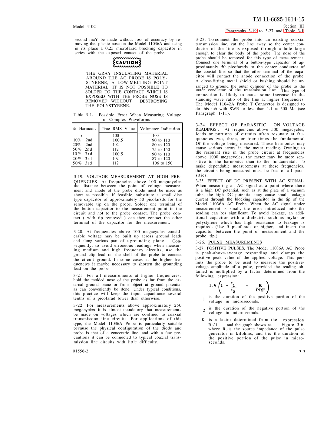
| Table | Possible Error When Measuring Voltage | |||
|
|
| of Complex Waveforms |
| |
| % Harmonic | , |
|
| |
|
|
| |||
| True RMS Value | Voltmeter Indication | |||
| o |
|
|
| |
|
| 100 | 100 | ||
10% | 2nd | 100.5 | 90 | to 110 | |
20% | 2nd | 102 | 80 | to 120 | |
50% | 2nd | 112 | 75 | to 150 | |
| l 0 % | 3 r d | 100.5 | 90 | to 110 |
| 2 0 % 3 r d | 102 | 87 | to 120 | |
5 0 % | 3 r d | 112 | 106 to 150 | ||
|
|
|
|
|
|
3-19. VOLTAGE MEASUREMENT AT HIGH FRE-
QUENCIES. At frequencies above 100 megacycles the distance between the point of voltage measure- ment and anode of the probe diode must be made as short as possible. If feasible, substitute a small disc type capacitor of approximately 50 picofarsds for the removable tip on the probe. Solder one terminal of the button capacitor to the measurement point in the circuit and not to the probe contact. The probe con- tact ( with tip removed ) can then contact the other terminal of the capacitor for the measurement.
and along various part of a grounding piane. Con- sequently, to avoid erroneous readings when measur- ing medium and high frequency circuits, use the ground clip lead on the shell of the probe to connect the circuit ground. In some cases at the higher fre- quencies it maybe necessary to shorten the grounding lead on the probe.
TM
Section III
Paragraphs
ranged to ground the outer cylinder of the probe to the outer conductor of the transmission line. This type of
connection is likely to cause some increase in the standing wave ratio of the line at higher frequencies. The Model 11042A Probe T Connector is designed to do this job with SWR or less than 1.1 at 500 Mc (see Paragraph
3 - 24 . EFFECT OF PARASITIC ON VOLTAGE READINGS . At frequencies above 500 megacycles, leads or portions of circuits often resonate at fre- quencies two, three, or four times the fundamental Of the voltage being measured. These harmonics may cause serious errors in the meter reading. Owning to the resonant rise in the probe circuit at frequencies above 1000 megacycles, the meter may be more sen- sitive to the harmonics than to the fundamental. To make dependable measurements at these frequencies, the circuits being measured must be free of ail para- sitics.
3-26. PULSE MEASUREMENTS
t1 is the duration of the positive portion of the voltage in microseconds.
t2 is the duration of the negative portion of the voltage in microseconds.
K is a | factor determined from the | expression |
R o/t1 | and the graph shown as | Figure |
where Ro is the source impedance of the pulse | ||
generator in kilohms, and tl is the | duration of | |
the positive portion of the pulse in micro- seconds.
