TM
Model 410C
instrument circuitry in an effort to localize the pro- blem. These operations should be undertaken only after it has been established that the difficulty can not be eliminated by the Adjustment and Calibration Pro-
cedures, Paragraph | An investigation should | |
also be made | to insure that | the trouble is not a result |
of conditions | external to the | Model 410C. |
tions, or | any other | obvious conditions which | might |
suggest a | source of | trouble. |
|
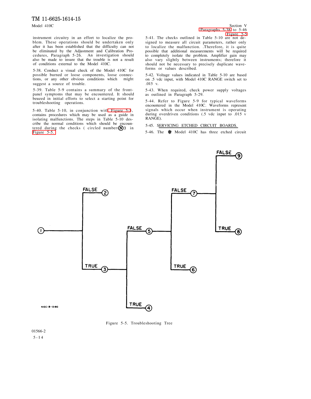
tered during the checks ( circled numbers in Figure
Section V Paragraphs
Figure 5-5 5-41. The checks outlined in Table 5-10 are not de-
signed to measure all circuit parameters, rather only to localize the malfunction. .Therefore, it is quite possible that additional measurements will be required to completely isolate the problem. Amplifier gain may also vary slightly between instruments; therefore it should not be necessary to precisely duplicate wave- forms or values described.
5-42. Voltage values indicated in Table 5-10 are based on .5 vdc input, with Model 410C RANGE switch set to
.015 v.
5-43. When required, check power supply voltages as outlined in Paragraph 5-29.
5-44. Refer to Figure 5-9 for typical waveforms encountered in the Model 410C. Waveforms represent signals which occur when instrument is operating during overdriven conditions (.5 vdc input to .015 v RANGE).
5-45. SERVICING ETCHED CIRCUIT BOARDS.
Model 410C has three etched circuit |
Figure 5-5. Troubleshooting Tree
01566-2
5 - 1 4