Section V
paragraphs
boards. Use caution when removing them to avoid
damaging mounted components. The ![]() Part Number for the assembly is silk screened on the interior of the circuit board to identify it. Refer to Section VI
Part Number for the assembly is silk screened on the interior of the circuit board to identify it. Refer to Section VI
for parts replacement and ![]() Part Number information
Part Number information
a.Use a
b. Circuit components can be removed by placing the soldering iron on the component lead on either aide of the board, and pulling up on lead. If a component is obviously damaged, clip leads as close to component as possible and then remove. Excess heat can cause the
circuit | and board to separate, or cause damage |
to the | component. |
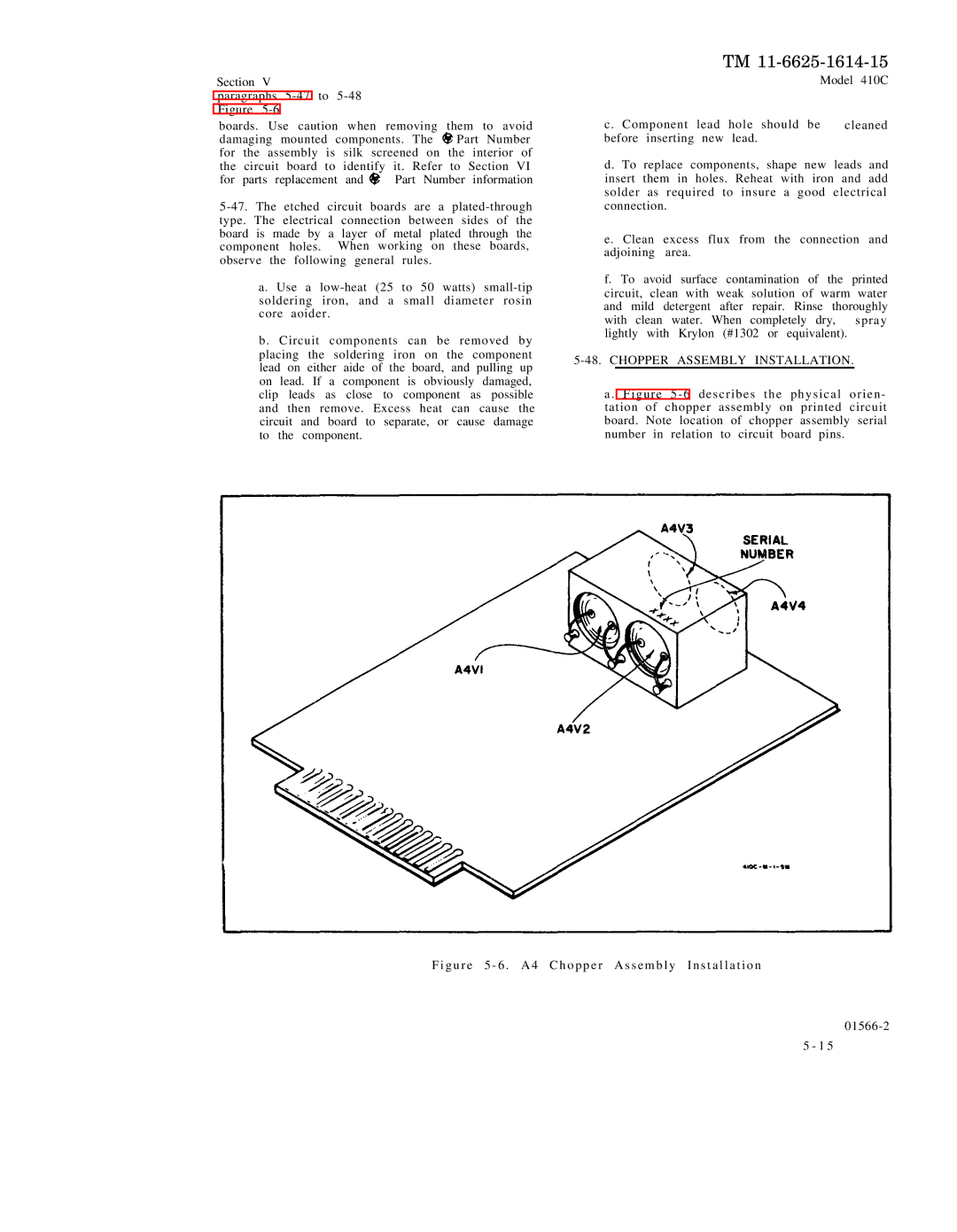
F i g u r e 5 - 6 . A 4
TM
Model 410C
c. Component | lead | hole should be | cleaned |
before inserting | new | lead. |
|
d. To replace components, shape new leads and insert them in holes. Reheat with iron and add solder as required to insure a good electrical connection.
e. Clean excess flux from the connection and adjoining area.
f. To avoid surface contamination of the printed circuit, clean with weak solution of warm water and mild detergent after repair. Rinse thoroughly
with clean water. When completely dry, spray lightly with Krylon (#1302 or equivalent).
5-48. CHOPPER ASSEMBLY INSTALLATION.
a . Figure 5 - 6 describes the physical orien - tation of chopper assembly on printed circuit board. Note location of chopper assembly serial number in relation to circuit board pins.
C h o p p e r A s s e m b l y I n s t a l l a t i o n
01566-2
5 - 1 5