TM
Section | III | Model 410C |
Figure |
|
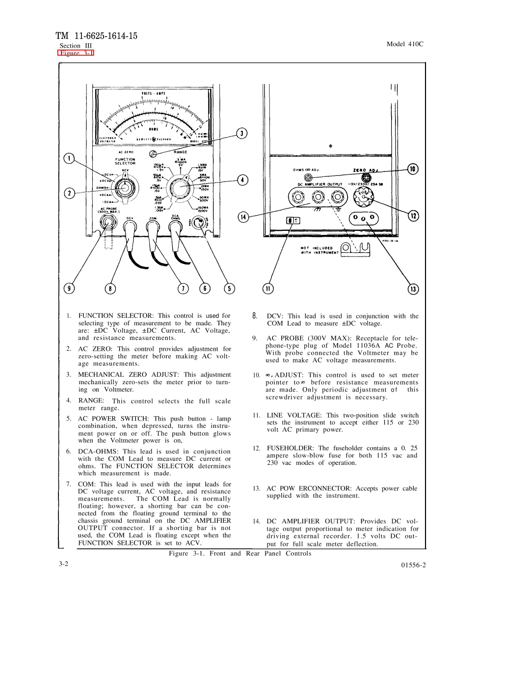
1.FUNCTION SELECTOR: This control is used for selecting type of measurement to be made. They are: ±DC Voltage, ±DC Current, AC Voltage, and resistance measurements.
2.AC ZERO: This control provides adjustment for
3.MECHANICAL ZERO ADJUST: This adjustment mechanically
4.RANGE: This control selects the full scale meter range.
5.AC POWER SWITCH: This push button - lamp combination, when depressed, turns the instru- ment power on or off. The push button glows when the Voltmeter power is on,
6.
7.COM: This lead is used with the input leads for DC voltage current, AC voltage, and resistance
measurements. The COM Lead is normally floating; however, a shorting bar can be con- nected from the floating ground terminal to the chassis ground terminal on the DC AMPLIFIER OUTPUT connector. If a shorting bar is not used, the COM Lead is floating except when the FUNCTION SELECTOR is set to ACV.
8.DCV: This lead is used in conjunction with the COM Lead to measure ±DC voltage.
9.AC PROBE (300V MAX): Receptacle for tele-
10.![]() ADJUST: This control is used to set meter
ADJUST: This control is used to set meter
pointer to ![]() before resistance measurements are made. Only periodic adjustment o f this screwdriver adjustment is necessary.
before resistance measurements are made. Only periodic adjustment o f this screwdriver adjustment is necessary.
11.LINE VOLTAGE: This
12.FUSEHOLDER: The fuseholder contains a 0. 25 ampere
13.AC POW ERCONNECTOR: Accepts power cable supplied with the instrument.
14.DC AMPLIFIER OUTPUT: Provides DC vol- tage output proportional to meter indication for driving external recorder. 1.5 volts DC out- put for full scale meter deflection.
Figure 3-1. Front and Rear Panel Controls
|
