| TM |
Model 410C | Section V |
| Parsgraphs |
| Figure |
.
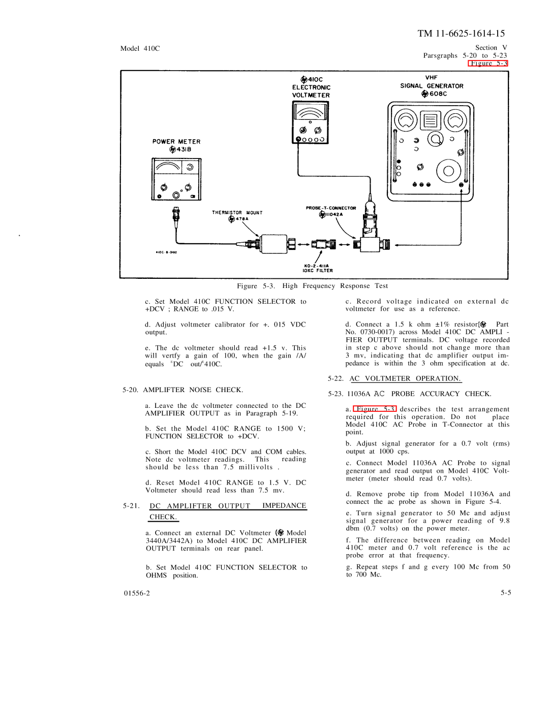
Figure 5-3. High Frequency Response Test
c. Set Model 410C FUNCTION SELECTOR to +DCV ; RANGE to .015 V.
d. Adjust voltmeter calibrator for +. 015 VDC output.
e. The dc voltmeter should read +1.5 v. This will vertfy a gain of 100, when the gain /A/ equals E DC out/E 410C.
5-20. AMPLIFTER NOfSE CHECK.
a. Leave the dc voltmeter connected to the DC AMPLIFIER OUTPUT as in Paragraph 5-19.
b. Set the Model 410C RANGE to 1500 V; FUNCTION SELECTOR to +DCV.
c. Short the Model 410C DCV and COM cables.
Note dc voltmeter readings. This reading should be less than 7 . 5 millivolts .
d. Reset Model 410C RANGE to 1.5 V. DC Voltmeter should read less than 7.5 mv.
5-21. DC AMPLIFTER OUTPUT IMPEDANCE
CHECK.
a. Connect an external DC Voltmeter ![]() Model 3440A/3442A) to Model 410C DC AMPLIFIER OUTPUT terminals on rear panel.
Model 3440A/3442A) to Model 410C DC AMPLIFIER OUTPUT terminals on rear panel.
b. Set Model 410C FUNCTION SELECTOR to OHMS position.
c . Record voltage indicated on external dc voltmeter for use as a reference.
d. Connect a 1.5 k ohm ±1% resistor ![]() Part No.
Part No.