Step 3
Step 4
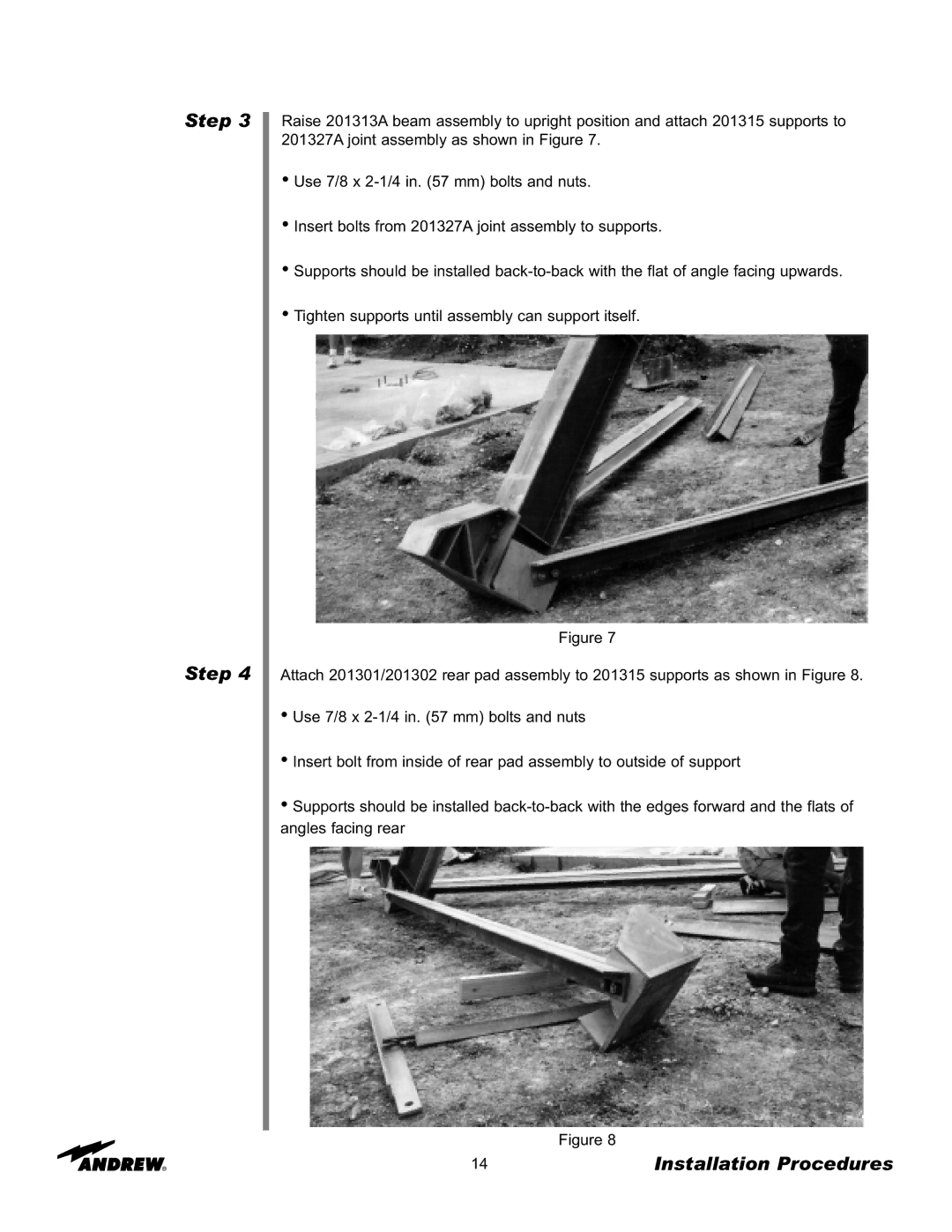
Raise 201313A beam assembly to upright position and attach 201315 supports to 201327A joint assembly as shown in Figure 7.
•Use 7/8 x
•Insert bolts from 201327A joint assembly to supports.
•Supports should be installed
•Tighten supports until assembly can support itself.
Figure 7
Attach 201301/201302 rear pad assembly to 201315 supports as shown in Figure 8.
•Use 7/8 x
•Insert bolt from inside of rear pad assembly to outside of support
•Supports should be installed
Figure 8
14 | Installation Procedures |