Step 4
Step 5
Step 6
Step 7
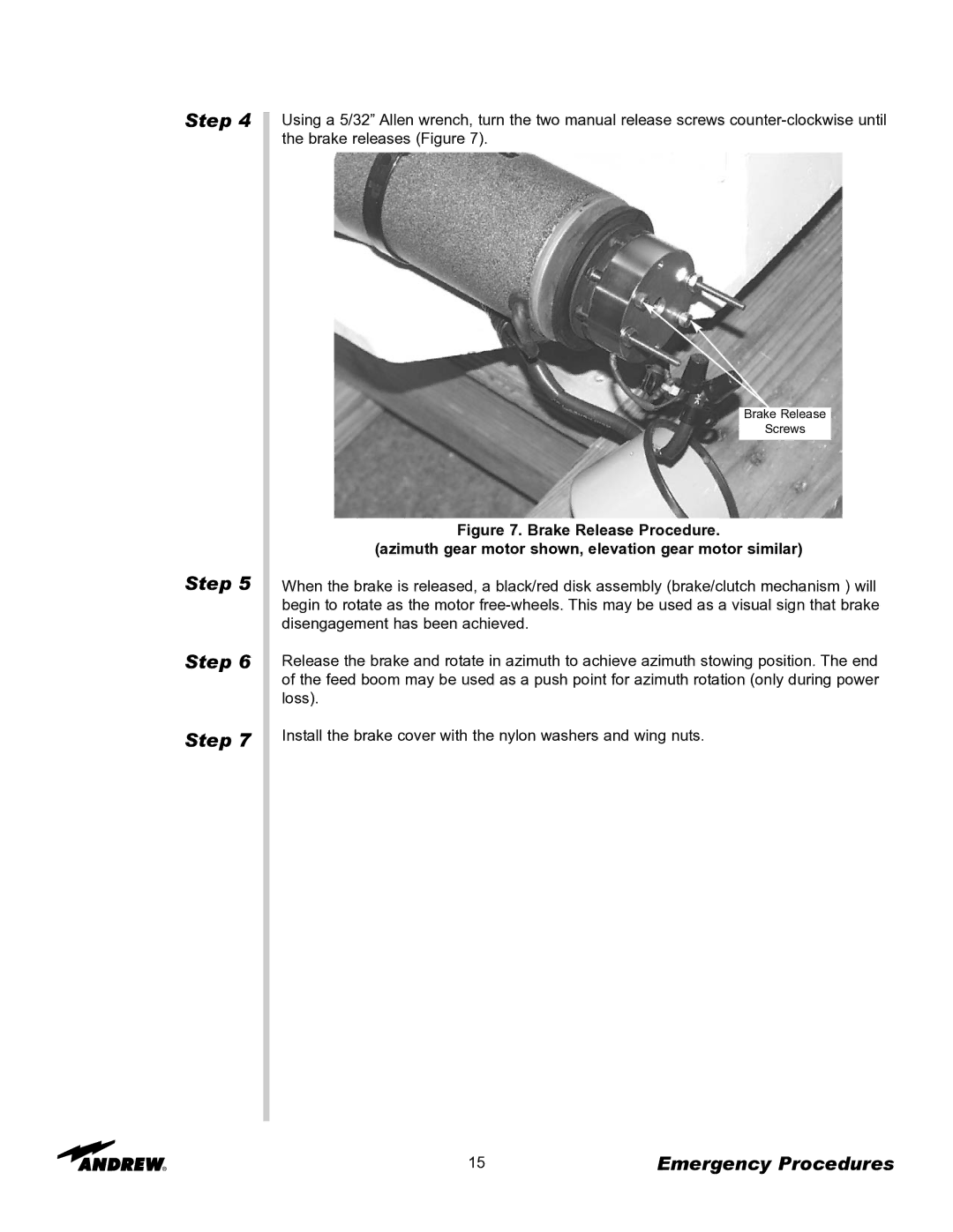
Using a 5/32” Allen wrench, turn the two manual release screws
Brake Release
Screws
Figure 7. Brake Release Procedure.
(azimuth gear motor shown, elevation gear motor similar)
When the brake is released, a black/red disk assembly (brake/clutch mechanism ) will begin to rotate as the motor
Release the brake and rotate in azimuth to achieve azimuth stowing position. The end of the feed boom may be used as a push point for azimuth rotation (only during power loss).
Install the brake cover with the nylon washers and wing nuts.
15 | Emergency Procedures |