Ordering Information (continued)
Manuals
Quick Start Guide
Related Literature, Application Notes
Waveguide Calibration Components and WG/ Coaxial Adapters
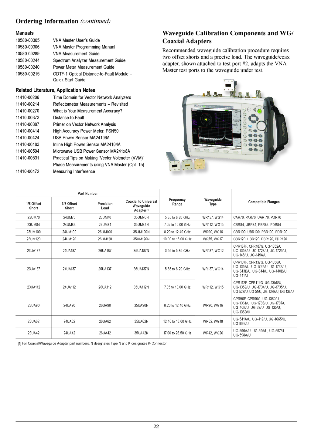
Recommended waveguide calibration procedure requires two offset shorts and a precise load. The waveguide/coax adapter, shown attached to test port #2, adapts the VNA Master test ports to the waveguide under test.
|
| Part Number |
|
|
|
| |
|
|
|
|
| Frequency | Waveguide |
|
1/8 Offset | 3/8 Offset |
| Precision | Coaxial to Universal | Compatible Flanges | ||
| Range | Type | |||||
| Waveguide |
| |||||
Short | Short |
| Load |
|
|
| |
| Adapter[1] |
|
|
| |||
|
|
|
|
|
|
| |
|
|
|
|
|
|
|
|
23UM70 | 24UM70 |
| 26UM70 | 35UM70N | 5.85 to 8.20 GHz | WR137, WG14 | CAR70, PAR70, UAR 70, PDR70 |
|
|
|
|
|
|
|
|
23UM84 | 24UM84 |
| 26UM84 | 35UM84N | 7.05 to 10.00 GHz | WR112, WG15 | CBR84, UBR84, PBR84, PDR84 |
|
|
|
|
|
|
|
|
23UM100 | 24UM100 |
| 26UM100 | 35UM100N | 8.20 to 12.40 GHz | WR90, WG16 | CBR100, UBR100, PBR100, PDR100 |
|
|
|
|
|
|
|
|
23UM120 | 24UM120 |
| 26UM120 | 35UM120N | 10.00 to 15.00 GHz | WR75, WG17 | CBR120, UBR120, PBR120, PDR120 |
|
|
|
|
|
|
|
|
|
|
|
|
|
|
| CPR187F, CPR187G, |
23UA187 | 24UA187 |
| 26UA187 | 35UA187N | 3.95 to 5.85 GHz | WR187, WG12 | |
|
|
|
|
|
|
| |
|
|
|
|
|
|
|
|
|
|
|
|
|
|
| CPR137F, CPR137G, |
23UA137 | 24UA137 |
| 26UA137 | 35UA137N | 5.85 to 8.20 GHz | WR137, WG14 | |
| |||||||
|
|
|
|
|
|
| |
|
|
|
|
|
|
| |
|
|
|
|
|
|
|
|
|
|
|
|
|
|
| CPR112F, CPR112G, |
23UA112 | 24UA112 |
| 26UA112 | 35UA112N | 7.05 to 10.00 GHz | WR112, WG15 | |
|
|
|
|
|
|
| |
|
|
|
|
|
|
|
|
|
|
|
|
|
|
| CPR90F, CPR90G, |
23UA90 | 24UA90 |
| 26UA90 | 35UA90N | 8.20 to 12.40 GHz | WR90, WG16 | |
| |||||||
|
|
|
|
|
|
| |
|
|
|
|
|
|
| |
|
|
|
|
|
|
|
|
23UA62 | 24UA62 |
| 26UA62 | 35UA62N | 12.40 to 18.00 GHz | WR62, WG18 | |
| UG1666/U | ||||||
|
|
|
|
|
|
| |
|
|
|
|
|
|
|
|
23UA42 | 24UA42 |
| 26UA42 | 35UA42K | 17.00 to 26.50 GHz | WR42, WG20 | |
| |||||||
|
|
|
|
|
|
| |
|
|
|
|
|
|
| |
[1] For Coaxial/Waveguide Adapter part numbers, N designates Type N and K designates |
|
| |||||
22
