VNA Master Functional Specifications
Definitions
•All specifications and characteristics apply under the following conditions, unless otherwise stated:
•After 30 minutes of
•Temperature range is 23 ºC ± 5 ºC.
•All specifications apply when using internal reference.
•All specifications subject to change without notice. Please visit www.us.anritsu.com for most current data sheet.
•Typical performance is the measured performance of an average unit.
•Recommended calibration cycle is 12 months.
Frequency
VNA Master Frequency Range: | MS2026/36C: | 5 kHz to 6 GHz |
| MS2028/38C: | 5 kHz to 20 GHz |
Frequency Accuracy: | 1.5 ppm |
|
Frequency Resolution: | 1 Hz to 375 MHz, 10 Hz to 6 GHz, and 100 Hz to 20 GHz | |
Typical Test Port Power
VNA Master supports selection of either High (default) or Low test port power. Changing power after calibration can degrade the calibrated performance. Typical power by bands is shown in the following table.
Frequency Range | High Port Power | Low Port Power | |
(dB) | (dBm) | ||
| |||
|
|
| |
5 kHz to ≤ 3 GHz | +3 | ||
|
|
| |
3 GHz to ≤ 6 GHz | |||
|
|
| |
6 GHz to ≤ 20 GHz | |||
|
|
|
Transmission Dynamic Range
The transmission dynamic range (the difference between test port power and noise floor) using 10 Hz IF Bandwidth and High Port Power is shown in the following table.
Frequency Range | Dynamic Range | |
(dB) | ||
| ||
|
| |
5 kHz to ≤ 2 MHz | 85 | |
|
| |
2 MHz to ≤ 3 GHz | 100 | |
|
| |
3 GHz to ≤ 6 GHz | 90 | |
|
| |
6 GHz to ≤ 20 GHz | 85 | |
|
|
Typical Sweep Speed
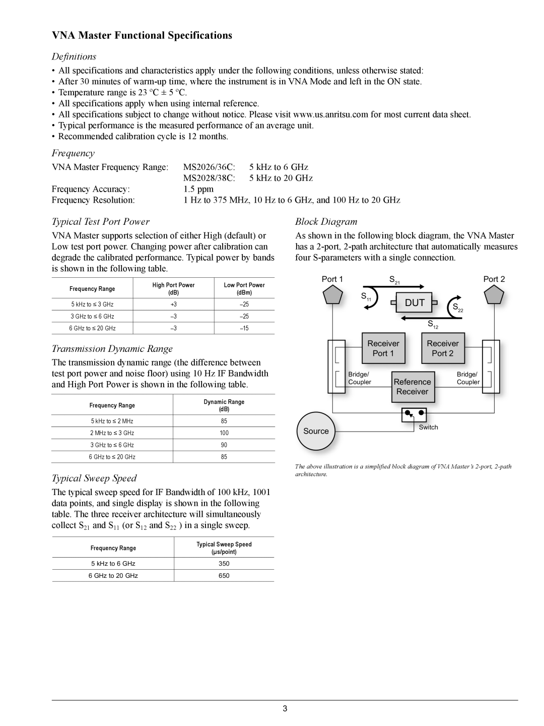
The typical sweep speed for IF Bandwidth of 100 kHz, 1001 data points, and single display is shown in the following table. The three receiver architecture will simultaneously collect S21 and S11 (or S12 and S22 ) in a single sweep.
Frequency Range | Typical Sweep Speed | |
(µs/point) | ||
| ||
|
| |
5 kHz to 6 GHz | 350 | |
|
| |
6 GHz to 20 GHz | 650 | |
|
|
Block Diagram
As shown in the following block diagram, the VNA Master has a
Port 1 |
| S21 |
|
|
|
| Port 2 | ||
S11 |
|
|
|
|
|
|
|
| |
|
|
| DUT |
| S22 | ||||
|
|
|
| ||||||
|
|
|
|
|
| ||||
|
|
|
|
|
|
|
| ||
|
|
|
|
|
|
| |||
|
|
|
|
|
| S12 |
| ||
| Receiver |
| Receiver |
| |||||
|
| Port 1 |
|
| Port 2 |
| |||
|
|
|
|
|
|
|
|
|
|
Bridge/ |
| Reference |
| Bridge/ | |||||
Coupler |
|
| Coupler | ||||||
Receiver
Source | Switch |
|
The above illustration is a simplified block diagram of VNA Master’s
