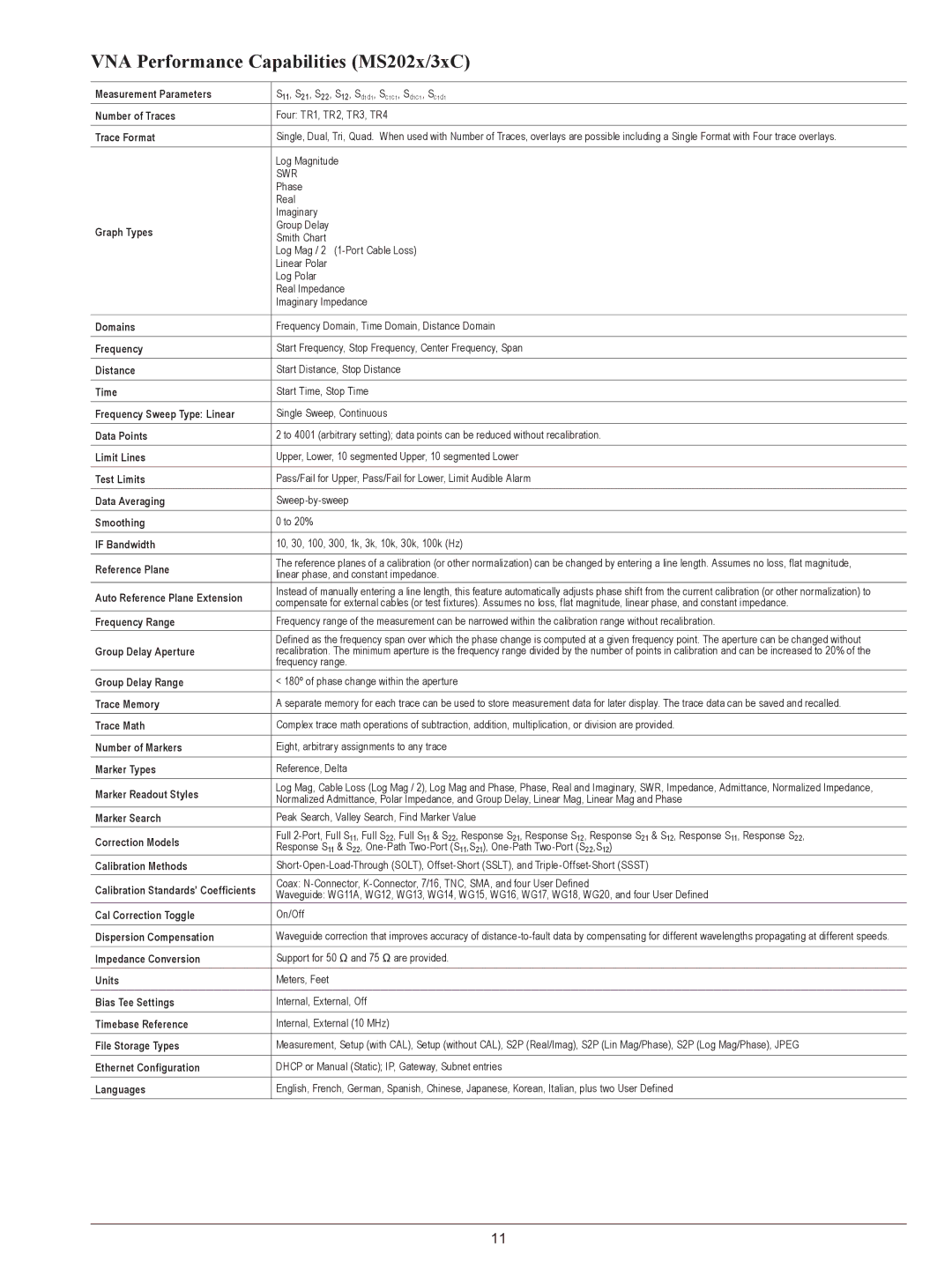
VNA Performance Capabilities (MS202x/3xC)
Measurement Parameters | S11, S21, S22, S12, Sd1d1, Sc1c1, Sd1c1, Sc1d1 | |
Number of Traces | Four: TR1, TR2, TR3, TR4 | |
|
| |
Trace Format | Single, Dual, Tri, Quad. When used with Number of Traces, overlays are possible including a Single Format with Four trace overlays. | |
|
| |
| Log Magnitude | |
| SWR | |
| Phase | |
| Real | |
| Imaginary | |
Graph Types | Group Delay | |
Smith Chart | ||
| ||
| Log Mag / 2 | |
| Linear Polar | |
| Log Polar | |
| Real Impedance | |
| Imaginary Impedance | |
|
| |
Domains | Frequency Domain, Time Domain, Distance Domain | |
|
| |
Frequency | Start Frequency, Stop Frequency, Center Frequency, Span | |
|
| |
Distance | Start Distance, Stop Distance | |
|
| |
Time | Start Time, Stop Time | |
|
| |
Frequency Sweep Type: Linear | Single Sweep, Continuous | |
|
| |
Data Points | 2 to 4001 (arbitrary setting); data points can be reduced without recalibration. | |
|
| |
Limit Lines | Upper, Lower, 10 segmented Upper, 10 segmented Lower | |
|
| |
Test Limits | Pass/Fail for Upper, Pass/Fail for Lower, Limit Audible Alarm | |
|
| |
Data Averaging | ||
|
| |
Smoothing | 0 to 20% | |
|
| |
IF Bandwidth | 10, 30, 100, 300, 1k, 3k, 10k, 30k, 100k (Hz) | |
|
| |
Reference Plane | The reference planes of a calibration (or other normalization) can be changed by entering a line length. Assumes no loss, flat magnitude, | |
linear phase, and constant impedance. | ||
| ||
Auto Reference Plane Extension | Instead of manually entering a line length, this feature automatically adjusts phase shift from the current calibration (or other normalization) to | |
compensate for external cables (or test fixtures). Assumes no loss, flat magnitude, linear phase, and constant impedance. | ||
| ||
Frequency Range | Frequency range of the measurement can be narrowed within the calibration range without recalibration. | |
| Defined as the frequency span over which the phase change is computed at a given frequency point. The aperture can be changed without | |
Group Delay Aperture | recalibration. The minimum aperture is the frequency range divided by the number of points in calibration and can be increased to 20% of the | |
| frequency range. | |
Group Delay Range | < 180º of phase change within the aperture | |
|
| |
Trace Memory | A separate memory for each trace can be used to store measurement data for later display. The trace data can be saved and recalled. | |
|
| |
Trace Math | Complex trace math operations of subtraction, addition, multiplication, or division are provided. | |
|
| |
Number of Markers | Eight, arbitrary assignments to any trace | |
|
| |
Marker Types | Reference, Delta | |
|
| |
Marker Readout Styles | Log Mag, Cable Loss (Log Mag / 2), Log Mag and Phase, Phase, Real and Imaginary, SWR, Impedance, Admittance, Normalized Impedance, | |
Normalized Admittance, Polar Impedance, and Group Delay, Linear Mag, Linear Mag and Phase | ||
| ||
Marker Search | Peak Search, Valley Search, Find Marker Value | |
|
| |
Correction Models | Full | |
Response S11 & S22, | ||
| ||
Calibration Methods | ||
|
| |
Calibration Standards’ Coefficients | Coax: | |
Waveguide: WG11A, WG12, WG13, WG14, WG15, WG16, WG17, WG18, WG20, and four User Defined | ||
| ||
Cal Correction Toggle | On/Off | |
|
| |
Dispersion Compensation | Waveguide correction that improves accuracy of | |
|
| |
Impedance Conversion | Support for 50 Ω and 75 Ω are provided. | |
|
| |
Units | Meters, Feet | |
|
| |
Bias Tee Settings | Internal, External, Off | |
|
| |
Timebase Reference | Internal, External (10 MHz) | |
|
| |
File Storage Types | Measurement, Setup (with CAL), Setup (without CAL), S2P (Real/Imag), S2P (Lin Mag/Phase), S2P (Log Mag/Phase), JPEG | |
|
| |
Ethernet Configuration | DHCP or Manual (Static); IP, Gateway, Subnet entries | |
|
| |
Languages | English, French, German, Spanish, Chinese, Japanese, Korean, Italian, plus two User Defined | |
|
|
11
