Manuals
/
Antex electronic
/
Home Audio
/
Satellite Radio
Antex electronic
XM-100
owner manual
Line Level, CN1 CN2 TBER #.# #.# ###
Models:
XM-100
1
16
26
26
Download
26 pages
50.66 Kb
13
14
15
16
17
18
19
20
Install
Optimizing Signal Strength
Warranty
SAVE 044 TO PRESET NO.?
Setup Menus Mode to Exit
Force Tuning Setup Sw Version
Safety
Page 16
Image 16
Page 15
Page 17
Page 16
Image 16
Page 15
Page 17
Contents
XM-100Commercial XM Satellite Radio
? Setting and Recalling Presets
IMPORTANT SAFETY INSTRUCTIONS
FCC Compliance Statement for United States Users
or circuits as contact with them might be fatal
Installing XM-100
Connections
Positioning the Antenna
For Outdoor installation or indoor wall mounting
Optimizing Signal Strength
CN1 CN2 TBER 9.0 8.5 12%
Operating the XM-100
?Setup Indicator - illuminated when in Setup Mode
Changing Channels
SAVE 044 TO PRESET NO.?
Setting and Recalling Presets
Changing Categories
Navigating Setup Menus
Setup Menus Mode to Exit
SETUP MENUS MODE TO EXIT
SETUP SIGNAL QUAL SETUP LINE LEVEL
SETUP FRONT LOCK SETUP TIME ZONE SETUP DLT SAVING
SETUP CH BLOCKING SETUP CH SKIPPING SETUP
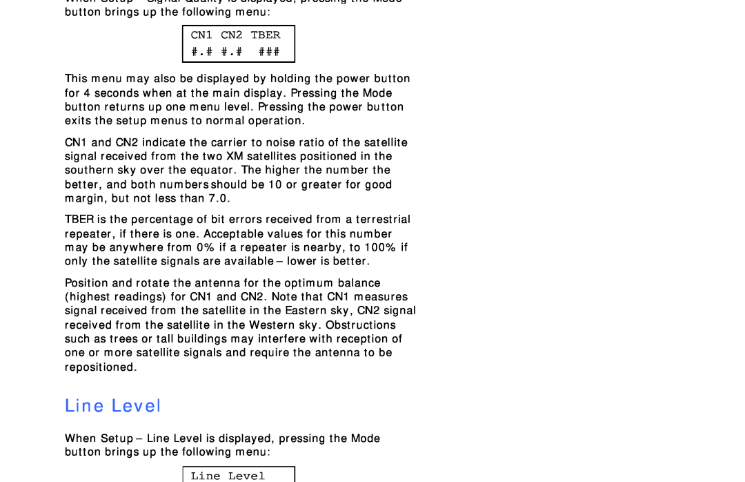
CN1 CN2 TBER #.# #.# ###
Line Level
Line Level
Front Lock
Time Zone
Front Lock? Locked
Timezone? Pacific
SETUP DST OBSERVE? Y
SETUP DST Y MAR 2 NOV
SETUP DST SPRG FWD MAR
SETUP DST FALL BK NOV
SETUP DST FALL BK W
Channel Blocking
Block ###? N PWR Toggles
Forced Tuning
Skip ###? N PWR Toggles
Force Tuning by Time Force Tuning by Channel
Force Tuning Add New
F46 C021 C Mon 11 45A
Page
PRESET
CHANNEL
MODE Press number to
NUMERIC
Audio Control System
12 Month Limited Warranty
Technical Assistance
Antex Electronics Corporation
Top
Page
Image
Contents