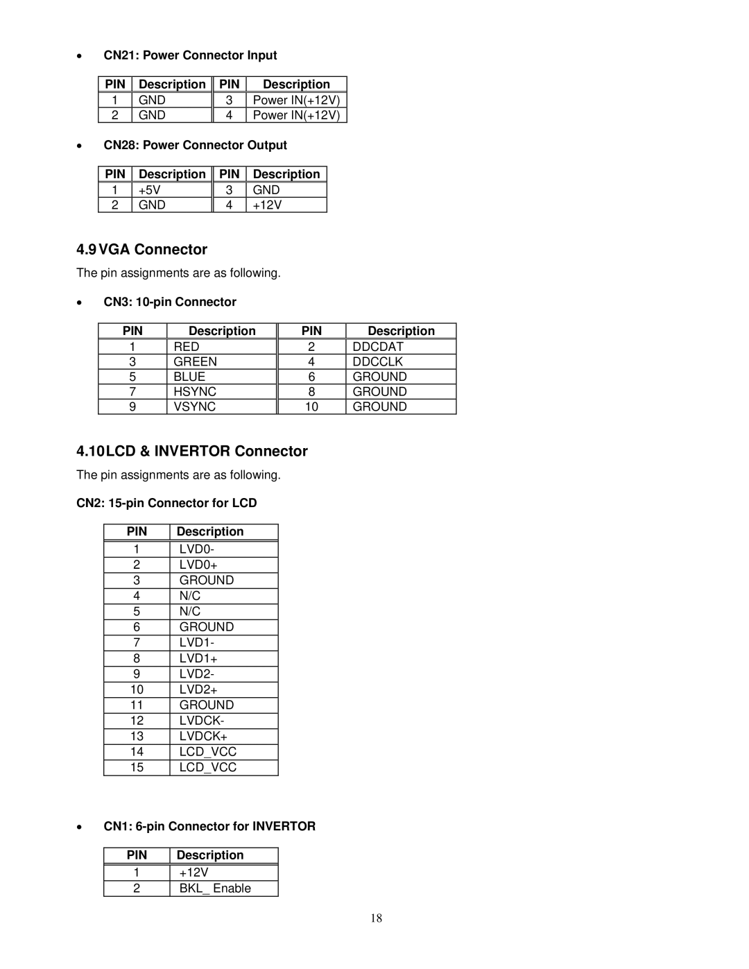
• CN21: Power Connector Input
| PIN | Description | PIN | Description | |
| 1 | GND | 3 | Power IN(+12V) | |
| 2 | GND | 4 | Power IN(+12V) | |
• CN28: Power Connector Output | |||||
|
|
|
|
|
|
| PIN | Description | PIN | Description |
|
| 1 | +5V | 3 | GND |
|
| 2 | GND | 4 | +12V |
|
4.9VGA Connector
The pin assignments are as following.
•CN3:
PIN | Description | PIN | Description |
1 | RED | 2 | DDCDAT |
3 | GREEN | 4 | DDCCLK |
5 | BLUE | 6 | GROUND |
7 | HSYNC | 8 | GROUND |
9 | VSYNC | 10 | GROUND |
4.10LCD & INVERTOR Connector
The pin assignments are as following.
CN2:
PIN | Description |
|
|
1 | LVD0- |
2 | LVD0+ |
3 | GROUND |
4 | N/C |
5 | N/C |
6 | GROUND |
7 | LVD1- |
8 | LVD1+ |
9 | LVD2- |
10 | LVD2+ |
11 | GROUND |
12 | LVDCK- |
13 | LVDCK+ |
14 | LCD_VCC |
15 | LCD_VCC |
•CN1:
PIN
Description
1+12V
2BKL_ Enable
18